
Class 12: Physics Chapter 7 solutions. Complete Class 12 Physics Chapter 7 Notes.
Contents
NCERT Solutions for 12th Class Physics: Chapter 7-Alternating Current
NCERT 12th Physics Chapter 7, Class 12 Physics Chapter 7 solutions
Question 1.
A 100 Q resistor is connected to a 220 V, 50 Hz a.c. supply.
(a) What is the rms value of current in the circuit?
(b) What is the net power consumed over a full cycle?
Solution:
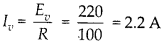
(a) Here virtual a.c. voltage is 220 V at a frequency of 50 Hz. So, rms value of current

(b) Power in complete cycle

Question 2.
(a) The peak voltage of an a.c. supply is 300 V. What is the rms voltage?
(b) The rms value of current in an a.c. circuit is 10 A. What is the peak current?
Solution:
(a) The peak value of a.c. supply is given 300 V.

Question 3.
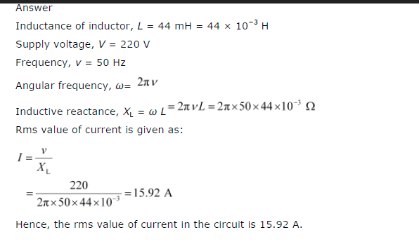
A 44 mH inductor is connected to 220 V, 50 Hz ac supply. Determine the rms value of current in the circuit.
Solution:
Question 4.
A 60 μF capacitor is connected to a 110 V, 60 Hz a.c. supply. Determine the rms value of current in the circuit.
Solution:

Question 5.
In previous questions 3 and 4, what is the net power absorbed by each circuit over a complete cycle. Explain your answer.
Solution:
For question 3, Power in the circuit with pure inductor P = Eυlυ cos π/2 = 0. For question 4, Power in complete cycle P = Eυlυ cos (-π/2) = 0.
Question 6.
Obtain the resonant frequency a), of a series LCR circuit with L = 2.0 H, C = 32 μF and R = 10 Ω2. What is the Q-value of this circuit?
Solution:
Resonant angular frequency in series LCR circuit

Question 7.
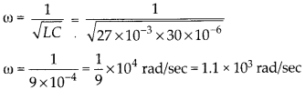
A charged 30 pF capacitor is connected to a 27 mH inductor. What is the angular frequency of free oscillations of the circuit?
Solution:
Angular frequency of LC oscillations
Question 8.
Suppose the initial charge on the capacitor given in question 7 is 6 mC. What is the total energy stored in the circuit initially? What is the total energy at later time?
Solution:
Initial energy on capacitor
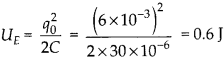
Any time total energy in the circuit is constant, hence energy later is 0.6 J.
Question 9.
A series LCR circuit with R = 20 Ω 2, L = 1.5 H and C = 35 μF is connected to a variable-frequency 200 V ac supply. When the frequency of the supply equals the natural frequency of the circuit, what is the average power transferred to the circuit in one complete cycle?
Solution:
Average power transferred to the circuit in one complete cycle at resonance


NCERT 12th Physics Chapter 7, Class 12 Physics Chapter 7 solutions
Question 10.
A radio can tune over the frequency range of a portion of MW broadcast band: (800 kHz to 1200 kHz), if its LC circuit has an effective inductance of 200 μH, what must be the range of its variable capacitor?
Solution:
For tuning, the natural frequency i.e., the frequency of L-C oscillations should be equal to frequency of radio waves received by the antenna in the form of same frequency current in the L-C circuit. For tuning at 800 kHz, required capacitance
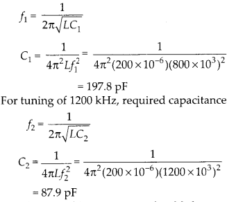
So, the variable capacitor should have a frequency range between 87.9 pF to 197.8 pF.
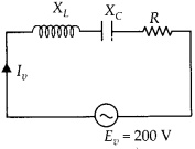
Question 11.
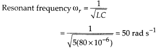
Figure shows a series LCR circuit connected to a variable frequency 230 V source. L = 5.0 H. C = 80 μF, ft = 40 Q

(a) Determine the source frequency which drives the circuit in resonance.
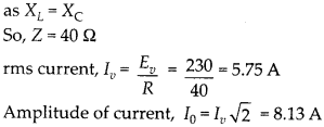
(b) Obtain the impedance of the circuit and the amplitude of current at the resonating frequency.
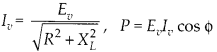
(c) Determine the rms potential drops across -the three elements of the circuit. Show that the potential drop across the LC combination is zero at the resonating
Solution:
(a) Condition for resonance is when applied frequency matches with natural frequency.
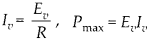
(b) At resonance, impedance Z = R
(c) Potential drop across ‘L’
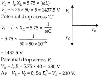
Question 12.
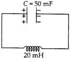
An LC circuit contains a 20 mH inductor and a 50 μF capacitor with initial charge of 10 mC. The resistance of the circuit in negligible. Let the instant the circuit is closed be t = 0.
(a) What is the total energy stored initially? Is it conserved during LC oscillations?
(b) What is the natural frequency of the circuit?
(c) At what time is the energy stored
- completely electrical (i.e., stored in the capacitor)?
- completely magnetic (i.e., stored in the inductor)?
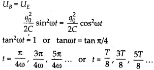
(d) At what times is the total energy shared equally between the inductor and capacitor?
(e) If a resistor is inserted in the circuit, how much energy is eventually dissipated as heat?
Solution:
(a) Total energy is initially in the form of electric field within the plates of charged capacitor.

If we neglect the losses due to resistance of connecting wires, the total energy remain consumed during LC oscillations.
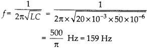
(b) Natural frequency of the circuit
(c) Instantaneous electrical energy
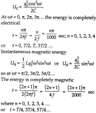
(d) timings for energy shared equally between inductor and capacitor.
(e) When a resistor is inserted in the circuit, eventually all the energy will be lost as heat across resistance. The oscillation will be damped.
NCERT 12th Physics Chapter 7, Class 12 Physics Chapter 7 solutions
Question 13.
A coil of inductance 0.50 H and resistance 100 Ω2 is connected to a 240 V. 50 Hz ac supply.
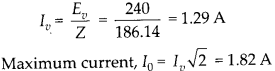
(a) What is the maximum current in the coil?
(b) What is the time lag between the voltage maximum and the current maximum?
Solution:
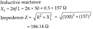
(a) Virtual current in the coil
(b)

Question 14.
Obtain the answers (a) and (b) in Q. 13, if the circuit is connected to a high frequency supply (240 V, 10 kHz). Hence, explain the statement that at very high frequency, an inductor in a circuit nearly amounts to an open circuit. How does an inductor behave in a dc circuit after the steady state?
Solution:
At very high frequency, XL increases to infinitely large, hence circuit behaves as open circuit.

(a) Current in the coil, lrms =


This current is extremely small. Thus, at high frequencies, the inductive reactance of an inductor is so large that it behaves as an open circuit.
(b)

In dc circuit (after steady state), v = 0 and as such XL = 0. In this case, the inductor behaves like a pure resistor as it has no inductive reactance.
Question 15.
A 100 μF capacitor in series with a 40 Q resistance is connected to a 110 V, 60 Hz supply.
(a) What is the maximum current in the circuit?
(b) What is the time lag between the current maximum and the voltage maximum?
Solution:
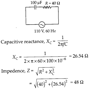
(a) Virtual current in the coil
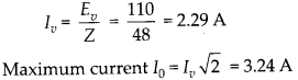
(b)

Question 16.
Obtain the answer to (a) and (b) in Q.15 if the circuit is connected to a 110 V, 12 kHz supply? Hence, explain the statement that a capacitor is a conductor at very high frequencies. Compare this behaviour with that of a capacitor in a dc circuit after the steady state.
Solution:
Given,

(a)

This value of current is same as that without capacitor in the circuit. So, at high frequency, a capacitor offer negligible resistance (0.1326 Ω in this case), it behave like a conductor.
(b)
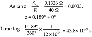
In dc circuit, after steady state, v = 0 and accordingly, XC = ∞, i.e., a capacitor amounts to an open circuit, i.e., it is a perfect insulator of current.
NCERT 12th Physics Chapter 7, Class 12 Physics Chapter 7 solutions
Question 17.
Keeping the source frequency equal to the resonating frequency of the series LCR circuit, if the three elements, L, C and R are arranged in parallel, show that the total current in the parallel LCR circuit is minimum at this frequency. Obtain the current rms value in each branch of the circuit for the elements of frequency. Source has emf 230 V and L = 5.0 H, C = 80 μF, ff = 40 Ω2.
Solution:
impedance of R and X in parallel is given by
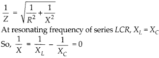
Thus, impedance Z = R and will be maximum. Hence, in parallel resonant circuit, current is minimum at resonant frequency. Current through circuit elements
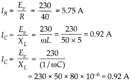
Since, IL and IC are opposite in phase, so net current,
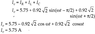
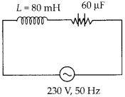
Question 18.
A circuit containing a 80 mH inductor and a 60 μF capacitor in series is connected to a 230 V, 50 Hz supply. The resistance of the circuit is negligible.
(a) Obtain the current amplitude and rms values.
(b) Obtain the rms values of potential drops across each element.
(c) What is the average power transferred to the inductor?
(d) What is the average power transferred to the capacitor.
(e) What is the total average power absorbed by the circuit? [‘Average’implies’averaged over one cycle’.
Solution:
(a) Inductive reactance , XL = 2πƒL

(b) Potential drop across L, VL = lυXL X
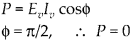
(c) Average power transferred to inductor is zero, because of phase difference π/2
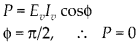
(d) Average power transferred to capacitor is also zero, because of phase difference π/2
(e) total power absorbed by the circuit

Question 19.
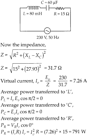
Suppose the circuit in Q. 18 has a resistance of 15 Ω2. Obtain the average power transferred to each element of the circuit and the total power absorbed.
Solution:
If the circuit has a resistance of 15 Ω2, now it is LCR series resonant circuit.
Question 20.
A series LCR circuit with L = 0.12 H, C = 480 μF, R = 23 Ω2 is connected to a 230 V variable frequency supply.
(a) What is the source frequency for which current amplitude is maximum. Obtain this maximum value.
(b) What is the source frequency for which average power absorbed by the circuit is maximum. Obtain the value of this maximum power.
(c) For which frequencies of the source is the power transferred to the circuit half the power at resonant frequency? What is the current amplitude at these frequencies?
(d) What is the Q-factor of the given circuit?
Solution:

(a) At resonant frequency, the current amplitude is maximum.

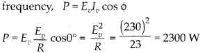
(b) Maximum power loss at resonant frequency, P = Eυlυ cos θ
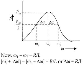
(c) Let at an angular frequency, the source power is half the power at resonant frequency.


Question 21.
Obtain the resonant frequency and Q-factor of a series LCR circuit with L = 3.0 H, C= 27 μF, and R = 7.4 fl. It is desired to improve the sharpness of the resonance of the circuit by reducing its ‘full width at half maximum’ by a factor of 2. Suggest a suitable way.
Solution:

we want to improve the quality factor to twice, without changing resonant frequency (without changing L and C).

Question 22.
Answer the following questions.
(a) In any ac circuit, is the applied instantaneous voltage equal to the algebraic sum of the instantaneous voltages across the series elements of the circuit? Is the same true for rms voltage?
(b) A capacitor is used in the primary circuit of an induction coil.
(c) An applied voltage signal consists of a superposition of a dc voltage and an ac voltage of high frequency. The circuit consists of an inductor and a capacitor in series. Show that the dc signal will appear across Cand the ac signal across L.
(d) A choke coil in series with a lamp is connected to a dc line. The lamp is seen to shine brightly. Insertion of an iron core in the choke causes no change in the lamp’s brightness. Predict the corresponding observations if the connection is to an ac line.
(e) Why is choke coil needed in the use of fluorescent tubes with ac mains? Why can we not use an ordinary resistor instead of the choke coil?
Solution:
(a) It is true that applied instantaneous voltage is equal to algebraic sum of instantaneous potential drop across each circuit element is series.

But the rms voltage applied is equal to vector sum of potential drop across each element, as voltage drops are in different phases.

(b) At the time of broken circuit of the induction coil, the induced high voltage charges the capacitor. This avoid sparking in the circuit.
(c) Inductive reactance, XL = 2πƒL For a.c., Xc α ƒ
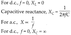
So, superimpose applied voltage will have all d.c. potential drop across Xc and will have most of a.c potential drop across XL.
(d) Inductor offer no hinderance to d.c. XL = 0, so insertion of iron core does not effect the d.c. current or brightness of lamp connected. But it definitely effect a.c. current as insertion of iron core increases L = μm nl thus increases XL (2πƒL). A.c. current in the E circuit reduces IP =

and brightness of the bulb also reduces.
(e) A fluorescent tube is connected directly across a 220 V source, it would draw large current which may damage the filaments of the tube. So a choke coil which behaves as L-R circuit reduces the current to appropriate value, and that also with a lesser power loss.
An ordinary resistor used to control the current would have maximum power wastage as heat.
Question 23.
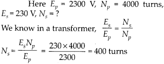
A power transmission line feeds input power at 2300 V to a step down transformer with its primary winding having 4000 turns. What should be the number of turns in the secondary in order to get output power at 230 V?
Solution:
Question 24.
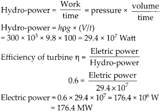
At a hydroelectric power plant, the water pressure head is at a height of 300 m and the water flow available is 100 m3s-1. If the turbine generator efficiency is 60%, estimate the electric power available from the plant (g = 9.8 ms-2).
Solution:
Work done by liquid pressure = pressure x volume shifted power of flowing water
Question 25.
A small town with a demand of 800 kW of 1 electric power at 220 V is situated 15 km away from an electric plant generating power at 440V. The resistance of the two wire line carrying power is 0.5 Q per km. The town gets 1 power from the line through a 4000-220 V step- down transformer at a sub station in the town.
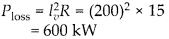
(a) Estimate the line power loss in the form of heat.
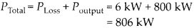
(b) How much power must the plant supply, assuming there is negligible power loss due to leakage?
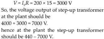
(c) Characterize the step up transformer at the plant.
Solution:
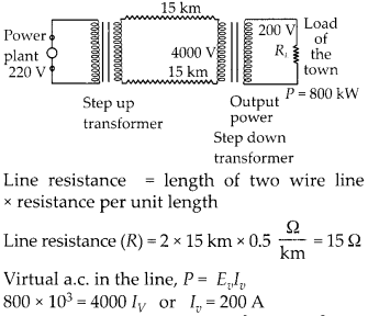
(a) Line power loss,
(b) Assuming no power loss due to leakage, total power need to be supply by the power plant

(c) Potential drop in the line,
Question 26.
Repeat the same exercise as in the previous question with the replacement of the earlier transformer by a 40,000-220 V step down transformer. (Neglect, as before, leakage losses through this may not be a good assumption any longer because of the very high voltage transmission involved). Hence, explain why high voltage transmission is preferred?
Solution:

(a) Line power loss,

(b) Power supplied by the plant
(c) Voltage drop in the line,
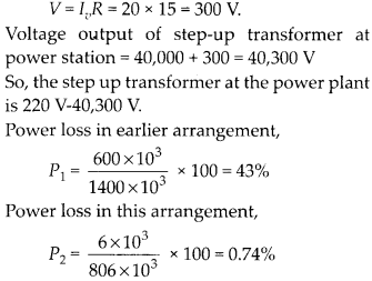
So, by supply of electricity at higher voltage, 40,000 V instead by 4000 V the power loss is reduced greatly that is why the electric power is always transmitted at very high voltage.
NCERT Solutions for 12th Class Physics: Chapter 7: Download PDF
NCERT Solutions for 12th Class Physics: Chapter 7-Alternating Current
Download PDF: NCERT Solutions for 12th Class Physics: Chapter 7-Alternating Current PDF
Chapterwise NCERT Solutions for Class 12 Physics :
- Chapter 1: Electric Charges and Fields
- Chapter-2: Electrostatic Potential and Capacitance
- Chapter 3: Current Electricity
- Chapter 4: Moving Charges and Magnetism
- Chapter 5: Magnetism and Matter
- Chapter 6: Electromagnetic Induction
- Chapter 7: Alternating Current
- Chapter 8: Electromagnetic Waves
- Chapter 9: Ray Optics And Optical Instruments
- Chapter 10: Wave Optics
- Chapter 11: Dual Nature Of Radiation And Matter
- Chapter 12: Atoms
- Chapter 13: Nuclei
- Chapter 14: Semiconductor Electronics Materials Devices And Simple Circuit
- Chapter 15: Communication Systems
About NCERT
The National Council of Educational Research and Training is an autonomous organization of the Government of India which was established in 1961 as a literary, scientific, and charitable Society under the Societies Registration Act. Its headquarters are located at Sri Aurbindo Marg in New Delhi. Visit the Official NCERT website to learn more.