
Class 12: Physics Chapter 3 solutions. Complete Class 12 Physics Chapter 3 Notes.
Contents
NCERT Solutions for 12th Class Physics: Chapter 3-Current Electricity
NCERT 12th Physics Chapter 3, Class 12 Physics Chapter 3 solutions
Question 1.
The storage battery of a car has an emf of 12 V. If the internal resistance of the battery is 0.4 Ω, what is the maximum current that can be drawn from the battery?
Solution:
The maximum current will be obtained when no external resistance is offered by wire joining the two terminals.

Question 2.
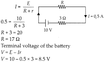
A battery of emf 10 V and internal resistance 3 Ω is connected to a resistor. If the current in the circuit is 0.5 A, what is the resistance of the resistor? What is the terminal voltage of the battery when the circuit is closed?
Solution:
Question 3.
(a) Three resistors 1 Ω, 2 Ω, and 3 Ω are combined in series. What is the total resistance of the combination?
(b) If the combination is connected to a battery of emf 12 V and negligible internal resistance, obtain the potential drop across each resistor.
Solution:
(a) Total resistance of the combination in series

Question 4.
(a) Three resistors 2Ω, 4Ω and 5Ω are combined in parallel. What is the total resistance of the combination?
(b) If the combination is connected to a battery of emf 20 V and negligible internal resistance. Determine the current through each resistor, and the total current drawn from the battery.
Solution:
(a) Total resistance of the combination in parallel
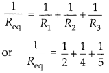

(b) Potential of 20 V will be same across each resistor, so current
Question 5.
At room temperature (27.0°C) the resistance of a heating element is 100 O. What is the temperature of the element if the resistance is found to be 117 Ω, given that the temperature coefficient of the material of the resistor is 1.70 × 10³ 0C-1.
Solution:

Question 6.
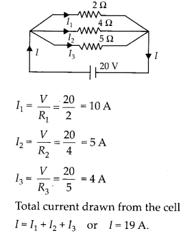
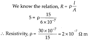
A negligibly small current is passed through a wire of length 15 m and uniform cross-section 6.0 × 10⁻⁷ m2, and its resistance is measured to be 5.0 Ω. What is the resistivity of the material at the temperature of the experiment?
Solution:
Question 7.
A silver wire has a resistance of 2.1 Ω, at 27.5°C and a resistance of 2.7 Ω at 100°C. Determine the temperature coefficient of resistivity of silver.
Solution:

Question 8.
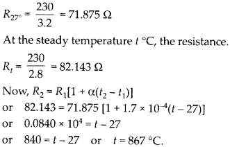
A heating element using nichrome connected to a 230 V supply draws an initial current of 3.2 A which settles after a few seconds to a steady value of 2.8 A. What is the steady temperature of the heating element if the room temperature is 27.0 °C ?Temperature coefficient of resistance of nichrome averaged over the temperature range involved is 1.70 × 10⁻⁴ °C-1.
Solution:
At room temperature 27 °C, the resistance of the heating element.
NCERT 12th Physics Chapter 3, Class 12 Physics Chapter 3 solutions
Question 9.
Determine the current in each branch of the network shown in figure.
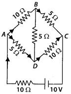
Solution:
Marti Let us first distribute the current in different branches. Now, eΩ actions for different loops using Kirchhoff’s IInd law,


Question 10.
(a) In a meter bridge as shown in figure, the balance point is found to be at 39.5 cm from the end A, when the resistor is of 12.5 Ω. Determine the resistance of x. Why are the connection between resistors in a Wheatstone or meter bridge made of thick copper strips?

(b) Determine the balance point of the bridge above if x and are interchanged.
(c) What happens if the galvanometer and cell are interchanged at the balance point of the bridge? Would the galvanometer show any current?
Solution:
(a)

The connections are made of thick copper strips so as to provide negligible resistance by connecting wires.
(b) If x and Y are interchanged the balance point will be at 60.5 cm from A.
(c) In balanced condition of the bridge, the cell and the galvanometer can be exchanged, the galvanometer will still show zero deflection.
Question 11.
A storage battery of emf 8.0 V and internal resistance 0.5 Ω is being charged by a 120 V dc supply using a series resistor of 15.5 Ω. What is the terminal voltage of the battery during charging? What is the purpose of having a series resistor in the charging circuit?
Solution:

Now, terminal voltage of the battery during charging
V = E + lr = 8 + 7(0.5) = 11.5 V A series resistance is joined in the charging circuit to limit the excessive current so that charging is slow and permanent.
Question 12.
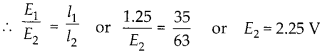
In a potentiometer arrangement, a cell of emf 1.25 V gives a balance point at 35.0 cm length of the wire. If cell is replaced by another cell and the balance point shifts to 63.0 cm, what is the emf of the second cell?
Solution:
The potential gradient remains the same, as there is no change in the setting of standard circuit.
Question 13.
The number density of free electrons in a copper conductor estimated is ,8.5 × 1028 m-3. How long does an electron take to drift from one end of a wire 3.0 m long to its other end? The area of cross-section of the wire is 2.0 × 10⁻⁶ m2 and it is carrying a current of 3.0 A.
Solution:
We can first calculate drift velocity of the electrons from the given data I = Aneud
NCERT 12th Physics Chapter 3, Class 12 Physics Chapter 3 solutions
Question 14.
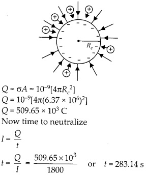
Theearth’s surface has a negative surface charge density of 10-9 cm-2. The potential difference of 400 kV between the top of the atmosphere and the surface results (due to the low conductivity of the lower atmosphere) in a current of only 1800 A over the entire globe. If there were no mechanism of sustaining atmospheric electric field, how much time (roughly) would be required to neutralise the earth’s surface? (This never happens in practice because there is a mechanism to replenish electric charges, namely the continual thunderstorms and lightning in different parts of the globe). (Radius of earth = 6.37 × 10⁶ m).
Solution:
Due to negative charge on earth, an electric field is into the earth surface due to which the positive ions of atmosphere are constantly pumped in and an equivalent current of 1800 A is established across the globe. Let us first calculate total negative charge on earth
Question 15.
(a) Six lead-acid type of secondary cells each of emf 2.0 V and internal resistance of 0.015 Ω are joined in series to provide a supply to a resistance of 8.5 Ω. What are the current drawn from the supply and its terminal voltage?
(b) A secondary cell after long use has an emf of 1.9 V and a large internal resistance of 380 Ω. What maximum current can be drawn from the cell ? Could the cell drive the starting motor of a car ?
Solution:
(a) Six cells are joined in series.
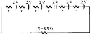
Equivalent emf is 2 × 6 = 12 V
Equivalent internal resistance is 0.015 × 6 = 0.09 Ω
Current drawn from supply

(b) Maximum current is drawn from a battery when external resistance is tested to be zero

To start a car, a current of the order of 100 A is needed, so the battery mentioned above can not drive the starting motor.
Question 16.
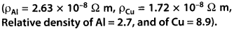
Two wires of equal length, one of aluminium and the other of copper have the same resistance. Which of the two wires is lighter? Hence explain why aluminium wires are preferred for overhead power cables.
Solution:
Two wires have same length, and resistance. As the specific resistances are unequal, the areas are different. For copper wire, Rcu = pcu


Thus, the aluminium wire for the same resistance is very light than copper and that is why aluminium wires are preferred for overhead power cables.
Question 17.
What conclusion can you draw from the following observations on a resistor made of alloy manning?
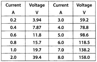
Solution:
We can find resistance of the alloy manganin for all the readings as follows :
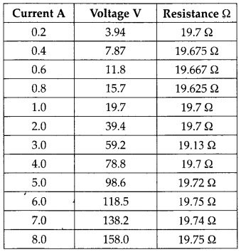
Here we can conclude that Ohm’s law is valid to a high accuracy and resistance of the alloy is nearly constant at all currents.
NCERT 12th Physics Chapter 3, Class 12 Physics Chapter 3 solutions
Question 18.
Answer the following questions:
- A steady current flows in a metallic conductor of non-uniform cross-section. Which of these quantities is constant along the conductor: current, current density, electric field, drift speed?
- Is Ohm’s law universally applicable for all conducting elements? If not, give examples of elements which do not obey Ohm’s law.
- A low voltage supply from which one needs high currents must have very low internal resistance. Why?
- A high tension (HT) supply of, say, 6 kV must have a large internal resistance. Why?
Solution:
- The current will be constant because it is given to be steady.

- Ohm’s law is not a fundamental law in nature. It is not universally followed. Semiconductor diodes, transistors, their mistors, vacuum tubes etc. do not follow Ohm’s law.
- If emf of supply battery is E and internal resistance r, then current through an external resistance R is given by
- so, internal resistance r should be least to supply high currents.
- In high tension supply, the internal resistance is made large. Because, if accidently the short circuiting take place, the excessive current produced should not cross the safety limits.
Question 19.
Choose the correct alternative:
- Alloys of metals usually have (greater/less) resistivity than that of their constituent metals.
- Alloys usually have much (lower/higher) temperature coefficients of resistance than pure metals.
- The resistivity of the alloy manganin is nearly independent of/increases rapidly with increase of temperature.
- The resistivity of a typical insulator (e.g., amber) is greater than that of a metal by a factor of the order of (1022 or 103).
Solution:
- Alloys of metals usually have greater resistivity than that of their constituent metals.
- Alloys usually have much lower temperature coefficients of resistance than pure metals.
- The resistivity of the alloy manganin is nearly independent of increasing temperature.
- The resistivity of a typical insulator (e.g. amber) is greater than that of a metal by factor of the order of 1022.
NCERT 12th Physics Chapter 3, Class 12 Physics Chapter 3 solutions
Question 20.
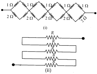
(a) Given n resistors each of resistance R, how will you combine them to get the
- maximum
- minimum effective resistance? What is the ratio of the maximum to minimum resistance?
(b) Given the resistances of 1 Ω, 2Ω, 3Ω, how will be combine them to get an equivalent resistance of
- (11/3) Ω
- (11/5) Ω,
- 6 Ω,
- (6/11) Ω?
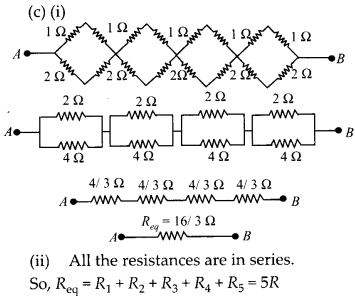
(c) Determine the equivalent resistance of network shown in figure.
Solution:
(a)
- For maximum effective resistance, all the resistors should be joined in series. Rmmax = R + R + R+……..n or Rmax = nR
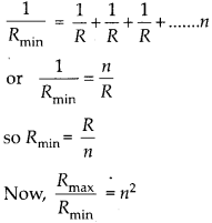
- For minimum effective resistance, all the resistors should be joined in parallel.
(b) All possible combinations with resistances 1 Ω, 2 Ω and 3 Ω are

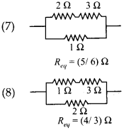
So, the combinations for the desired results can be selected.
Question 21.
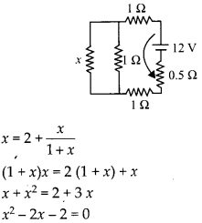
Determine the current drawn from a 12 V supply with internal resistance 0.5 Ω by the infinite network shown in figure. Each resistor has 1 Ω resistance.
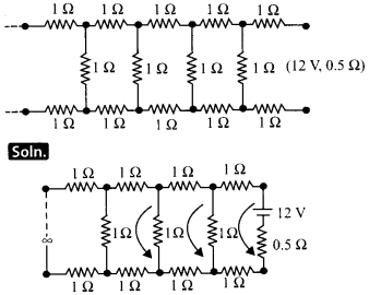
As shown in diagram the loop of resistance shown by arrow is repeated at times, let us assume the equivalent resistance is x, so by adding one more loop the resistance will remain as x.

NCERT 12th Physics Chapter 3, Class 12 Physics Chapter 3 solutions
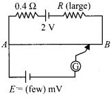
Question 22.
Figure shows a potentiometer with a cell of 2.0 V and internal resistance 0.40 Ω maintaining a potential drop across the resistor wire AB. A standard cell which maintains a constant emf of 1.02 V (for very moderate currents upto a few mA) gives a balance point at 67.3 cm length of the wire. To ensure very low currents drawn from the standard cell, a very high resistance of 600 kΩ is put in series with it, which is shorted close to the balance point. The standard cell is then replaced by a cell of unknown emf E and the balance point found similarly, turns out to be at 82.3 cm length of the wire.

- What is the value of E?
- What purpose does the high resistance of 600 kΩ have?
- Is the balance point affected by this high resistance?
- Is the balance point affected by the internal resistance of the driver cell?
- Would the method work in the above situation if the driver cell of the potentiometer had an emf of 1.0 V instead of 2.0 V?
- Would the circuit work well for determining an extremely small emf, say of the order of a few mV (such as the typical emf of a thermo-couple)? If not, how will you modify the circuit?
Solution:
- For emf of 1.02 V, the balance point is 67.3 cm of wire. For unknown emf E, the balance point is 82.3 cm of wire.

- A high resistance of 600 kΩ is joined in series with cell so as to prevent the galvanometer from excessive current, when the jockey is touched far from null point. Once the null point is closely known the 600 kΩ is short circuited so that exact position of null point can be achieved.
- In presence of high resistance we will obtain null point for a longer length then a sharp position, it is because of very low current near null point.
- Internal resistance of the cell do not affect the balance point, as no current is drawn at null point.
- If the driver cell of standard circuit has an emf smaller than emf of the cell to be balanced then null point will not be achieved in the length of potentiometer wire and galvanometer will provide only one side deflection always.
- In the given state, the circuit will be unsuitable, as for E of the order of mV the null point will be very close to end A and percentage error in the measurement of emf will be larger.
To make suitable arrangement the potential drop in potentiometer wire is brought down to few mV, so that balance point is obtained at suitable length and this is done by introducing a high resistance in series in the standard calibration circuit.
Question 23.
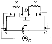
Figure shows a potentiometer circuit for comparison of two resistances. The balance point with a standard resistor R = 10.0 Ω is found to be 58.3 cm, while that with the unknown resistance x is 68.5 cm. Determine the value of x. What might you do if you failed to find a balance point with the given cell of emfε?

Solution:
For comparison of resistances, R and x should be in series and same current should flow through them.
If we fail to find balance point with cell of e.m.f. e, in that case we should reduce the current I and for that e.m.f. E of cell responsible for current I should reduce, or a resistor can also be attached in series with R and x to reduce current.
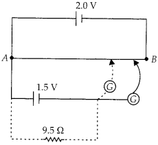
Question 24.
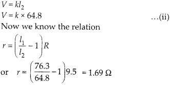
Figure shows a 2.0 V potentiometer used for the determination of internal resistance of a 1.5 V cell. The balance point of the cell in open circuit is 76.3 cm. When a resistor of 9.5 Ω is used in the external circuit of the cell, the balance point shifts to 64.8 cm length of the potentiometer wire. Determine the internal resistance of the cell.
Solution:
In the open circuit, the balance point is obtained for the emf of 1.5 V.

When the external circuit is connected, a current is drawn from the cell of 1.5 V in external resistance of 9.5 E1. Now the balance point is obtained for terminal potential
NCERT Solutions for 12th Class Physics: Chapter 3: Download PDF
NCERT Solutions for 12th Class Physics: Chapter 3-Current Electricity
Download PDF: NCERT Solutions for 12th Class Physics: Chapter 3-Current Electricity PDF
Chapterwise NCERT Solutions for Class 12 Physics :
- Chapter 1: Electric Charges and Fields
- Chapter-2: Electrostatic Potential and Capacitance
- Chapter 3: Current Electricity
- Chapter 4: Moving Charges and Magnetism
- Chapter 5: Magnetism and Matter
- Chapter 6: Electromagnetic Induction
- Chapter 7: Alternating Current
- Chapter 8: Electromagnetic Waves
- Chapter 9: Ray Optics And Optical Instruments
- Chapter 10: Wave Optics
- Chapter 11: Dual Nature Of Radiation And Matter
- Chapter 12: Atoms
- Chapter 13: Nuclei
- Chapter 14: Semiconductor Electronics Materials Devices And Simple Circuit
- Chapter 15: Communication Systems
About NCERT
The National Council of Educational Research and Training is an autonomous organization of the Government of India which was established in 1961 as a literary, scientific, and charitable Society under the Societies Registration Act. Its headquarters are located at Sri Aurbindo Marg in New Delhi. Visit the Official NCERT website to learn more.