NCERT Exemplar Class 12 Physics Chapter 7: Alternating Current. NCERT Exemplar Solutions for Class 12 Physics Chapter 7 Alternating Current prepare students for their Class 12 exams thoroughly.
Physics problems and solutions for the Class 12 pdf are provided here which are similar to the questions being asked in the previous year’s board.
Contents
NCERT Exemplar Class 12 Physics Chapter 7: Alternating Current
Class 12: Physics Chapter 7 solutions. Complete Class 12 Physics Chapter 7 Notes.
Multiple Choice Questions MCQ I
- If the rms current in a 50 Hz ac circuit is 5 A, the value of the current 1/300 seconds after its value becomes zero is
- (a) 5 √2 A
- (b) 5 √3/2 A
- (c) 5/6 A
- (d) 5/√2 A
- An alternating current generator has an internal resistance Rg and an internal reactance Xg. It is used to supply power to a passive load consisting of a resistance Rg and a reactance XL. For maximum power to be delivered from the generator to the load, the value of XL is equal to
- (a) zero.
- (b) Xg.
- (c) – Xg.
- (d) Rg.
- When a voltage measuring device is connected to AC mains, the meter shows the steady input voltage of 220V. This means
- (a) input voltage cannot be AC voltage, but a DC voltage.
- (b) maximum input voltage is 220V.
- (c) the meter reads not v but and is calibrated to read √< v2 >.
- (d) the pointer of the meter is stuck by some mechanical defect.
- To reduce the resonant frequency in an LCR series circuit with a generator
- (a) the generator frequency should be reduced.
- (b) another capacitor should be added in parallel to the first.
- (c) the iron core of the inductor should be removed.
- (d) dielectric in the capacitor should be removed.
- Which of the following combinations should be selected for better tuning of an LCR circuit used for communication?
- (a) R = 20 Ω, L = 1.5 H, C = 35μF.
- (b) R = 25 Ω, L = 2.5 H, C = 45μF.
- (c) R = 15 Ω, L = 3.5 H, C = 30μF.
- (d) R = 25 Ω, L = 1.5 H, C = 45μF.
- An inductor of reactance 1 Ω and a resistor of 2 Ω are connected in series to the terminals of a 6 V (rms) a.c. source. The power dissipated in the circuit is
- (a) 8 W.
- (b) 12 W.
- (c) 14.4 W.
- (d) 18 W.
- The output of a step-down transformer is measured to be 24 V when connected to a 12 watt light bulb. The value of the peak current is
- (a) 1/√2 A.
- (b) 2 A.
- (c) 2 A.
- (d) 2 √2 A.
Multiple Choice Questions MCQ II
- As the frequency of an ac circuit increases, the current first increases and then decreases. What combination of circuit elements is most likely to comprise the circuit?
- (a) Inductor and capacitor.
- (b) Resistor and inductor.
- (c) Resistor and capacitor.
- (d) Resistor, inductor and capacitor.
- In an alternating current circuit consisting of elements in series, the current increases on increasing the frequency of supply. Which of the following elements are likely to constitute the circuit ?
- (a) Only resistor.
- (b) Resistor and an inductor.
- (c) Resistor and a capacitor.
- (d) Only a capacitor.
- Electrical energy is transmitted over large distances at high alternating voltages. Which of the following statements is (are) correct?
- (a) For a given power level, there is a lower current.
- (b) Lower current implies less power loss.
- (c) Transmission lines can be made thinner.
- (d) It is easy to reduce the voltage at the receiving end using step-down transformers.
- For an LCR circuit, the power transferred from the driving source to the driven oscillator is P = I2Z cos φ.
- (a) Here, the power factor cos φ ≥ 0, P ≥ 0.
- (b) The driving force can give no energy to the oscillator (P = 0) in some cases.
- (c) The driving force cannot syphon out (P < 0) the energy out of oscillator.
- (d) The driving force can take away energy out of the oscillator.
- When an AC voltage of 220 V is applied to the capacitor C
- (a) the maximum voltage between plates is 220 V.
- (b) the current is in phase with the applied voltage.
- (c) the charge on the plates is in phase with the applied voltage.
- (d) power delivered to the capacitor is zero.
- The line that draws power supply to your house from street has
- (a) zero average current.
- (b) 220 V average voltage.
- (c) voltage and current out of phase by 90°.
- (d) voltage and current possibly differing in phase φ such that |φ| < π/2 .
Very Short Answer Type Questions
- If a LC circuit is considered analogous to a harmonically oscillating spring block system, which energy of the LC circuit would be analogous to potential energy and which one analogous to kinetic energy?
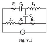
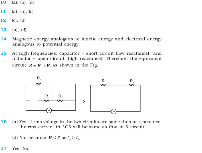
- Draw the effective equivalent circuit of the circuit shown in Fig 7.1, at very high frequencies and find the effective impedance.
- Study the circuits (a) and (b) shown in Fig 7.2 and answer the following questions.
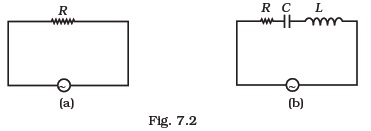
(a) Under which conditions would the rms currents in the two circuits be the same?
(b) Can the rms current in circuit (b) be larger than that in (a)? - Can the instantaneous power output of an ac source ever be negative? Can the average power output be negative?
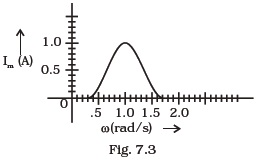
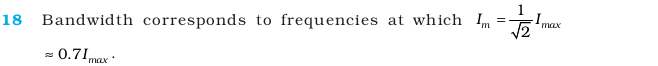
- In series LCR circuit, the plot of Imax vs ω is shown in Fig 7.3. Find the bandwidth and mark in the figure.
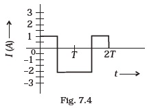
- The alternating current in a circuit is described by the graph shown in Fig 7.4 . Show rms current in this graph.
- How does the sign of the phase angle φ , by which the supply voltage leads the current in an LCR series circuit, change as the supply frequency is gradually increased from very low to very high values.
Short Answer Type Questions
- A device ‘X’ is connected to an a.c source. The variation of voltage, current and power in one complete cycle is shown in Fig 7.5.
(a) Which curve shows power consumption over a full cycle?
(b) What is the average power consumption over a cycle?
(c) Identify the device ‘X’.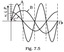
- Both alternating current and direct current are measured in amperes. But how is the ampere defined for an alternating current?
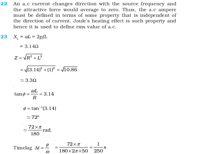
- A coil of 0.01 henry inductance and 1 ohm resistance is connected to 200 volt, 50 Hz ac supply. Find the impedance of the circuit and time lag between max. alternating voltage and current.
- A 60 W load is connected to the secondary of a transformer whose primary draws line voltage. If a current of 0.54 A flows in the load, what is the current in the primary coil? Comment on the type of transformer being used.
- Explain why the reactance provided by a capacitor to an alternating current decreases with increasing frequency.
- Explain why the reactance offered by an inductor increases with increasing frequency of an alternating voltage.
Long Answer Type Questions
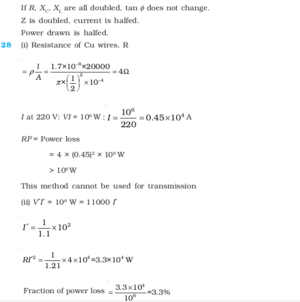
- An electrical device draws 2kW power from AC mains (voltage 223V (rms) = 50,000 V). The current differs (lags) in phase by
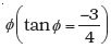 as compared to voltage. Find
(i) R,
(ii) XC – XL, and
(iii) IM. Another device has twice the values for R, XC and XL. How are the answers affected? - 1 MW power is to be delivered from a power station to a town 10 km away. One uses a pair of Cu wires of radius 0.5 cm for this purpose. Calculate the fraction of ohmic losses to power transmitted if
(i) power is transmitted at 220V. Comment on the feasibility of doing this.
(ii) a step-up transformer is used to boost the voltage to 11000 V, power transmitted, then a step-down transformer is used to bring voltage to 220 V.
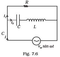
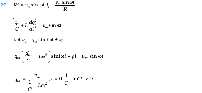
(ρ<sub<Cu1.7 x 10–8 SI unit) - Consider the LCR circuit shown in Fig 7.6. Find the net current i and the phase of i. Show that i = (v/z). Find the impedance Z for this circuit.
- For an LCR circuit driven at frequency ω, the equation reads L(di/dt) + Ri + (q/C) = vi = vmsinωt
(i) Multiply the equation by i and simplify where possible.
(ii) Interpret each term physically.
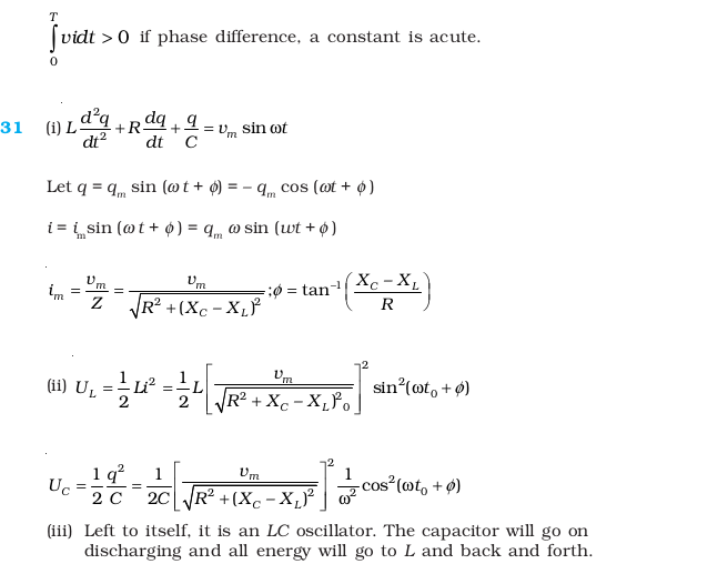
(iii) Cast the equation in the form of a conservation of energy statement.
(iv) Integrate the equation over one cycle to find that the phase difference between v and i must be acute. - In the LCR circuit shown in Fig 7.7, the ac driving voltage is v = vm sin ωt.(i) Write down the equation of motion for q (t).
(ii) At t = t0, the voltage source stops and R is short circuited. Now write down how much energy is stored in each of L and C.
(iii) Describe subsequent motion of charges.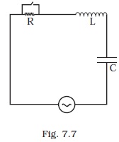
Answers to Multiple Choice Questions


NCERT Exemplar Class 12 Physics Solutions
Here we have provided NCERT Exemplar Problems Solutions along with NCERT Exemplar Problems Class 12. Physics Important Questions Class 12 are given below chapter-wise.
- Electric Charges and Fields
- Electrostatic Potential and Capacitance
- Current Electricity
- Moving Charges and Magnetism
- Magnetism and Matter
- Electromagnetic Induction
- Alternating Current
- Electromagnetic Waves
- Ray Optics and Optical Instruments
- Wave Optics
- Dual Nature of Radiation and Matter
- Atoms
- Nuclei
- Semiconductor Electronics: Materials, Devices, and Simple Circuits
- Communication Systems