
HC Verma Physics books are the most preferred books among students of CBSE schools. Students can be found referring to the chapters as well as practice questions at the end of each of these chapters, in the books. Students follow these textbooks religiously since quite a few questions in these also appear in exams.
Contents
- 1 HC Verma Solutions for Class 12 Physics Chapter 35 – Magnetic Field due to a Current
- 1.0.1 Page No 248:
- 1.0.2 Question 1:
- 1.0.3 Answer:
- 1.0.4 Question 2:
- 1.0.5 Answer:
- 1.0.6 Question 3:
- 1.0.7 Answer:
- 1.0.8 Question 4:
- 1.0.9 Answer:
- 1.0.10 Question 5:
- 1.0.11 Answer:
- 1.0.12 Question 6:
- 1.0.13 Answer:
- 1.0.14 Question 7:
- 1.0.15 Answer:
- 1.0.16 Question 8:
- 1.0.17 Answer:
- 1.0.18 Question 9:
- 1.0.19 Answer:
- 1.0.20 Question 10:
- 1.0.21 Answer:
- 1.0.22 Question 11:
- 1.0.23 Answer:
- 1.0.24 Question 12:
- 1.0.25 Answer:
- 1.0.26 Question 1:
- 1.0.27 Answer:
- 1.0.28 Question 2:
- 1.0.29 Answer:
- 1.0.30 Question 3:
- 1.0.31 Answer:
- 1.0.32 Question 4:
- 1.0.33 Answer:
- 1.0.34 Question 5:
- 1.0.35 Answer:
- 1.0.36 Question 6:
- 1.0.37 Answer:
- 1.0.38 Question 7:
- 1.0.39 Answer:
- 1.0.40 Page No 249:
- 1.0.41 Question 8:
- 1.0.42 Answer:
- 1.0.43 Question 9:
- 1.0.44 Answer:
- 1.0.45 Question 10:
- 1.0.46 Answer:
- 1.0.47 Question 11:
- 1.0.48 Answer:
- 1.0.49 Question 12:
- 1.0.50 Answer:
- 1.0.51 Question 1:
- 1.0.52 Answer:
- 1.0.53 Question 2:
- 1.0.54 Answer:
- 1.0.55 Question 3:
- 1.0.56 Answer:
- 1.0.57 Question 4:
- 1.0.58 Answer:
- 1.0.59 Question 5:
- 1.0.60 Answer:
- 1.0.61 Question 6:
- 1.0.62 Answer:
- 1.0.63 Question 7:
- 1.0.64 Answer:
- 1.0.65 Question 1:
- 1.0.66 Answer:
- 1.0.67 Question 2:
- 1.0.68 Answer:
- 1.0.69 Page No 250:
- 1.0.70 Question 3:
- 1.0.71 Answer:
- 1.0.72 Question 4:
- 1.0.73 Answer:
- 1.0.74 Question 5:
- 1.0.75 Answer:
- 1.0.76 Question 6:
- 1.0.77 Answer:
- 1.0.78 Question 7:
- 1.0.79 Answer:
- 1.0.80 Question 8:
- 1.0.81 Answer:
- 1.0.82 Question 9:
- 1.0.83 Answer:
- 1.0.84 Question 10:
- 1.0.85 Answer:
- 1.0.86 Question 11:
- 1.0.87 Answer:
- 1.0.88 Question 12:
- 1.0.89 Answer:
- 1.0.90 Question 13:
- 1.0.91 Answer:
- 1.0.92 Question 14:
- 1.0.93 Answer:
- 1.0.94 Question 15:
- 1.0.95 Answer:
- 1.0.96 Question 16:
- 1.0.97 Answer:
- 1.0.98 Question 17:
- 1.0.99 Answer:
- 1.0.100 Question 18:
- 1.0.101 Answer:
- 1.0.102 Page No 251:
- 1.0.103 Question 19:
- 1.0.104 Answer:
- 1.0.105 Question 20:
- 1.0.106 Answer:
- 1.0.107 Question 21:
- 1.0.108 Answer:
- 1.0.109 Question 22:
- 1.0.110 Answer:
- 1.0.111 Question 23:
- 1.0.112 Answer:
- 1.0.113 Question 24:
- 1.0.114 Answer:
- 1.0.115 Question 25:
- 1.0.116 Answer:
- 1.0.117 Question 26:
- 1.0.118 Answer:
- 1.0.119 Question 27:
- 1.0.120 Answer:
- 1.0.121 Question 28:
- 1.0.122 Answer:
- 1.0.123 Question 29:
- 1.0.124 Answer:
- 1.0.125 Question 30:
- 1.0.126 Answer:
- 1.0.127 Question 31:
- 1.0.128 Answer:
- 1.0.129 Question 32:
- 1.0.130 Answer:
- 1.0.131 Question 33:
- 1.0.132 Answer:
- 1.0.133 Question 34:
- 1.0.134 Answer:
- 1.0.135 Question 35:
- 1.0.136 Answer:
- 1.0.137 Page No 252:
- 1.0.138 Question 36:
- 1.0.139 Answer:
- 1.0.140 Question 37:
- 1.0.141 Answer:
- 1.0.142 Question 38:
- 1.0.143 Answer:
- 1.0.144 Question 39:
- 1.0.145 Answer:
- 1.0.146 Question 40:
- 1.0.147 Answer:
- 1.0.148 Question 41:
- 1.0.149 Answer:
- 1.0.150 Question 42:
- 1.0.151 Answer:
- 1.0.152 Question 43:
- 1.0.153 Answer:
- 1.0.154 Question 44:
- 1.0.155 Answer:
- 1.0.156 Question 45:
- 1.0.157 Answer:
- 1.0.158 Question 46:
- 1.0.159 Answer:
- 1.0.160 Question 47:
- 1.0.161 Answer:
- 1.0.162 Question 48:
- 1.0.163 Answer:
- 1.0.164 Question 49:
- 1.0.165 Answer:
- 1.0.166 Question 50:
- 1.0.167 Answer:
- 1.0.168 Question 51:
- 1.0.169 Answer:
- 1.0.170 Question 52:
- 1.0.171 Answer:
- 1.0.172 Question 53:
- 1.0.173 Answer:
- 1.0.174 Question 54:
- 1.0.175 Answer:
- 1.0.176 Question 55:
- 1.0.177 Answer:
- 1.0.178 Question 56:
- 1.0.179 Answer:
- 1.0.180 Page No 253:
- 1.0.181 Question 57:
- 1.0.182 Answer:
- 1.0.183 Question 58:
- 1.0.184 Answer:
- 1.0.185 Question 59:
- 1.0.186 Answer:
- 1.0.187 Question 60:
- 1.0.188 Answer:
- 1.0.189 Question 61:
- 1.0.190 Answer:
- 2 Chapterwise HC Verma Solutions Class 12 Physics :
- 3 About the Author – HC Verma
HC Verma Solutions for Class 12 Physics Chapter 35 – Magnetic Field due to a Current
For such popular books, students can get extremely helpful practice material online. For all the questions in the HC Verma books, there are several sources where students can get detailed solutions and solve their doubts and queries.
Please note that these solutions are provided here for free.
Page No 248:
Question 1:
An electric current flows in a wire from north to south. What will be the direction of the magnetic field due to this wire at a point (a) east of the wire, (b) west of the wire, (c) vertically above the wire and (d) vertically below the wire?
Answer:
According to the right-hand thumb rule, if the thumb of our right hand points in the direction of the current flowing, then the curling of the fingers will show the direction of the magnetic field developed due to it and vice versa. Let us consider the case where an electric current flows north to south in a wire.
According to the right-hand thumb rule,
(a) for any point in the east of the wire, the magnetic field will come out of the plane of paper
(b) for a point in the west of the wire, the magnetic field will enter the plane of paper
(c) for any point vertically above the wire, the magnetic field will be from right to left
(d) for any point vertically below the wire, the magnetic field will be from left to right
Question 2:
The magnetic field due to a long straight wire has been derived in terms of µ, i and d. Express this in terms of ε0, c, i and d.
Answer:
The magnetic field due to a long, straight wire is given by
B = μoi2πd∵Speed of light, c = 1μoεo⇒μo = 1c2εo⇒B = i2πc2εod(In terms of ε0, c, i and d)
Question 3:
You are facing a circular wire carrying an electric current. The current is clockwise as seen by you. Is the field at the centre coming towards you or going away from you?
Answer:
According to the right-hand thumb rule, if we curl the fingers of our right hand in the direction of the current flowing, then the thumb will point in the direction of the magnetic field developed due to it and vice versa. Therefore, in this case, the field at the centre is going away from us.
Question 4:
In Ampere’s
∮B→·dl→=μ0i,the current outside the curve is not included on the right hand side. Does it mean that the magnetic field B calculated by using Ampere’s law, gives the contribution of only the currents crossing the area bounded by the curve?
Answer:
In Ampere’s law
∮B→.dl → = μoi, i is the total current crossing the area bounded by the closed curve. The magnetic field B on the left-hand side is the resultant field due to all existing currents.
Question 5:
The magnetic field inside a tightly wound, long solenoid is B = µ0 ni. It suggests that the field does not depend on the total length of the solenoid, and hence if we add more loops at the ends of a solenoid the field should not increase. Explain qualitatively why the extra-added loops do not have a considerable effect on the field inside the solenoid.
Answer:
The magnetic field due to a long solenoid is given as B = µ0ni, where n is the number of loops per unit length. So, if we add more loops at the ends of the solenoid, there will be an increase in the number of loops and an increase in the length, due to which the ratio n will remain unvaried, thereby leading to not a considerable effect on the field inside the solenoid.
Question 6:
A long, straight wire carries a current. Is Ampere’s law valid for a loop that does not enclose the wire, or that encloses the wire but is not circular?
Answer:
Ampere’s law is valid for a loop that is not circular. However, it should have some charge distribution in the area enclosed so as to have a constant electric field in the region and a non-zero magnetic field. Even if the loop defined does not have its own charge distribution but has electric influence of some other charge distribution, it can have some constant magnetic field (
∮B→.dl→ = μoienclosed).
Question 7:
A straight wire carrying an electric current is placed along the axis of a uniformly charged ring. Will there be a magnetic force on the wire if the ring starts rotating about the wire? If yes, in which direction?
Answer:
The magnetic force on a wire carrying an electric current i is
F→=i.(l→×B→), where l is the length of the wire and B is the magnetic field acting on it. If a uniformly charged ring starts rotating around a straight wire, then according to the right-hand thumb rule, the magnetic field due to the ring on the current carrying straight wire placed at its axis will be parallel to it. So, the cross product will be
(l→×B→)=0⇒F→=0Therefore, no magnetic force will act on the wire.
Question 8:
Two wires carrying equal currents i each, are placed perpendicular to each other, just avoiding a contact. If one wire is held fixed and the other is free to move under magnetic forces, what kind of motion will result?
Answer:
The magnetic force on a wire carrying an electric current i is
F→=i.(l→×B→), ​where l is the length of the wire and B is the magnetic field acting on it. Suppose we have one wire in the horizontal direction (fixed) and other wire in the vertical direction (free to move). If the horizontal wire is carrying current from right to left is held fixed perpendicular to the vertical wire, which is free to move, the upper portion of the free wire will tend to move in the left direction and the lower portion of the wire will tend to move in the right direction, according to Fleming’s left hand rule, as the magnetic field acting on the wire due to the fixed wire will point into the plane of paper above the wire and come out of the paper below the horizontal wire and the current will flow in upward direction in the free wire. Thus, the free wire will tend to become parallel to the fixed wire so as to experience maximum attractive force.
Question 9:
Two proton beams going in the same direction repel each other whereas two wires carrying currents in the same direction attract each other. Explain.
Answer:
Two proton beams going in the same direction repel each other, as they are like charges and we know that like charges repel each other.
When a charge is in motion then a magnetic field is associated with it. Two wires carrying currents in the same direction produce their fields (acting on each other) in opposite directions so the resulting magnetic force acting on them is attractive. Due to the magnetic force, these two wires attract each other.
But when a charge is at rest then only an electric field is associated with it and no magnetic fiels is produced by it. So at rest, it repels a like charge by exerting a electric force on it.
Charge in motion can produce both electric field and magnetic field.
The attractive force between two current carrying wires is due to the magnetic field and repulsive force is due to the electric field.
Question 10:
In order to have a current in a long wire, it should be connected to a battery or some such device. Can we obtain the magnetic due to a straight, long wire by using Ampere’s law without mentioning this other part of the circuit?
Answer:
We can obtain a magnetic field due to a straight, long wire using Ampere’s law by mentioning the current flowing in the wire, without emphasising on the source of the current in the wire. To apply Ampere’s circuital law, we need to have a constant current flowing in the wire, irrespective of its source.
Question 11:
Quite often, connecting wires carrying currents in opposite directions are twisted together in using electrical appliances. Explain how it avoids unwanted magnetic fields.
Answer:
Connecting wires carrying currents in opposite directions are twisted together in using electrical appliances.If the wire is twisted, then the resultant fields from consecutive twists are in opposite directions. So the cumulative effect over a long length of wire is roughly zero.
Let at any point in between the two wires, B1 and B2 be the magnetic field due to wire 1 and wire 2 respectively.
From the diagram, we can see that the net magnetic field due to first turn is into the paper and due to second twisted turn is out of the plane of paper so these fields will cancel each other. Hence if the wire is twisted, then the resultant fields from consecutive twists are in opposite directions. So the cumulative effect over a long length of wire is roughly zero.
Question 12:
Two current-carrying wires may attract each other. In absence of other forces, the wires will moves towards each other increasing the kinetic energy. Does it contradict the fact that the magnetic force cannot do any work and hence cannot increase the kinetic energy?
Answer:
Magnetic field can not do any work and hence can never speed up or down a particle.
Consider 2 wires carrying current in upward direction.
Magnetic field due to current in wire 1 produces a magnetic field out of the plane of paper at the position of wire 2. Due to this magnetic field, a force is exerted on wire 2. Wire 2 electron, moving in downward direction, move in circular paths due to this magnetic force. As these electrons can not come out of the wire so while describing circular path,they hit the edges of the wire and tranfer a momentum to the wire. Due to this change in momentum, wire starts moving and gains kinetic energy.
Question 1:
A vertical wire carries a current in upward direction. An electron beam sent horizontally towards the wire will be deflected
(a) towards right
(b) towards left
(c) upwards
(d) downwards.
Answer:
(c) upwards
A vertical wire is carrying current in upward direction, so the magnetic field produced will be anticlockwise (according to the right-hand thumb rule). As the electron beam is sent horizontally towards the wire, the direction of the current will be horizontally away from the wire (direction of conventional current is opposite to the direction of the negative charge). According to Fleming’s left-hand rule, the force will act in upward direction, deflecting the beam in the same direction.
Question 2:
A current-carrying, straight wire is kept along the axis of a circular loop carrying a current. This straight wire
(a) will exert an inward force on the circular loop
(b) will exert an outward force on the circular loop
(c) will not exert any force on the circular loop
(d) will exert a force on the circular loop parallel to itself.
Answer:
(c) will not exert any force on the circular loop
The magnetic force on a wire carrying an electric current i is given as​
F→=i.(l→×B→), where l is the length of the wire and B is the magnetic field acting on it. If a current-carrying straight wire is kept along the axis of a circular loop carrying current, then according to the right-hand thumb rule, the magnetic field due to the wire on the current-carrying loop will be along its circumference, which contains a current element
i dl→.
So, the cross product will be​
(l→×B→)=0⇒F→=0Thus, the straight wire will not exert any force on the loop.
Question 3:
A proton beam is going from north to south and an electron beam is going from south to north. Neglecting the earth’s magnetic field, the electron beam will be deflected
(a) towards the proton beam
(b) away from the proton beam
(c) upwards
(d) downwards.
Answer:
(a) towards the proton beam
A proton beam is going from north to south, so the direction of the current due to the beam will also be from north to south. Also, an electron beam is going from south to north, so the direction of the current due to the beam will also be from north to south. The direction of conventional current is along the direction of the flow of the positive charge and opposite to the flow of the negative charge. The magnetic field generated due to them will enter the plane of paper in the west and come out of the plane of paper in the east, according to the right-hand thumb rule. Since both the beams have currents in the same direction, they will apply equal and opposite forces on each other and, hence, will attract each other. Thus, the electron beam will be deflected towards the proton beam.
Question 4:
A circular loop is kept in that vertical plane which contains the north-south direction. It carries a current that is towards north at the topmost point. Let A be a point on the axis of the circle to the east of it and B a point on this axis to the west of it. The magnetic field due to the loop
(a) is towards east at A and towards west at B
(b) is towards west at A and towards east at B
(c) is towards east at both A and B
(d) is towards west at both A and B
Answer:
(d) is towards west at both A and B
According to the right-hand thumb rule, if we curl the fingers of our right hand in the direction of the current flowing, then the stretching of the thumb will show the direction of the magnetic field developed due to it and vice versa.
Let north-south is along x axis and east-west is along y axis. Circular wire is in xz plane. Then point A will lie on positive y axis and B on negative y axis. On looking from point B, current is flowing in anticlockwise direction so the magnetic field will point from right to left. Hence, the magnetic field due to the loop will be towards west at both A and B.
Question 5:
Consider the situation shown in figure. The straight wire is fixed but the loop can move under magnetic force. The loop will
(a) remain stationary
(b) move towards the wire
(c) move away from the wire
(d) rotate about the wire.
Figure
Answer:
(b) move towards the wire

Force acting on the wire per unit length carrying current i2 due to the wire carrying current i1 placed at a distance d is given by
F = μoi1i22πdSo, forces per unit length acting on sides AB and CD are as follows:
FAB = μoi1i22πd (Towards the wire)FCD = μoi1i22π(d+a) (Away from the wire)Here, FAB > FCDbecause force is inversly proportional to the distance from the wire and wire AB is closer to the wire carrying current i1.
The forces per unit length acting on sides BC and DA will be equal and opposite, as they are equally away from the wire carrying current i1, with current i2flowing in the opposite direction.
∴ FBC=
-FDA
Now,
Net force:
F = FAB+FBC+FCD+FDA⇒F = μoi1i22πd+FBC-μoi1i22π(d+a)-FBC⇒F = μoi1i22π1d-1d+a⇒F = μoi1i2a2πd(d+a)(Towards the wire)
Therefore, the loop will move towards the wire.
Question 6:
A charged particle is moved along a magnetic field line. The magnetic force on the particle is
(a) along its velocity
(b) opposite to its velocity
(c) perpendicular to its velocity
(d) zero.
Answer:
(d) zero
The force on a charged particle q moving with velocity v in a magnetic field B is given by
F→=q(v→×B→)As the charge is moving along the magnetic line of force, the velocity and magnetic field vectors will point in the same direction, making a cross product.
(v→×B→) = 0⇒F→ = 0So, the magnetic force on the particle will be zero.
Question 7:
A moving charge produces
(a) electric field only
(b) magnetic field only
(c) both of them
(d) none of them.
Answer:
(c) both of them
Because of the presence of a charge, a particle produces an electric field. Also, because of its motion, that is, the flow of charge or current, there is generation of a magnetic field.
Page No 249:
Question 8:
A particle is projected in a plane perpendicular to a uniform magnetic field. The area bounded by the path described by the particle is proportional to
(a) the velocity
(b) the momentum
(c) the kinetic energy
(d) none of these.
Answer:
(c) the kinetic energy
When a particle of mass m carrying charge q is projected with speed v in a plane perpendicular to a uniform magnetic field B, the field tends to deflect the particle in a circular path of radius r.
∴mv2r = qvB⇒r = mvqBNow,Area, A = πr2⇒A = πmvqB2⇒A = kv2Here, k = πmqB2Kinetic energy of the particle,
E = 12mv2Therefore, the area bounded is proportional to the kinetic energy.
Question 9:
Two particles X and Y having equal charge, after being accelerated through the same potential difference enter a region of uniform magnetic field and describe circular paths of radii R1 and R2 respectively. The ratio of the mass of X to that of Y is
(a) (R1/R2)1/2
(b) R1/R2
(c) (R1/R2)2
(d) R1R2.
Answer:
(c)
R12R22Particles X and Y of respective masses m1 and m2 are carrying charge q describing circular paths with respective radii R1 and R2 such that
R1 = m1v1qBR2 = m2v2qBSince both the particles are accelerated through the same potential difference, both will have the same kinetic energy.
∴12m1v12 = 12m2v22∵R1=m1v1qB⇒v1 = R1qBm1And,R2 = m2v2qB ⇒v2 = R2qBm2∴m1R1qBm12 = m2R2qBm22⇒m1m2 = R12R22
Question 10:
Two parallel wires carry currents of 20 A and 40 A in opposite directions. Another wire carying a current anti parallel to 20 A is placed midway between the two wires. T he magnetic force on it will be
(a) towards 20 A
(b) towards 40 A
(c) zero
(d) perpendicular to the plane of the currents.
Answer:
(b) towards 40 A
​According to Fleming’s left-hand rule, if the forefinger and middle finger of our left hand point towards the magnetic field acting on a wire and the current flowing in the wire, respectively, then the thumb will point towards the direction in which the force will act (keeping all three perpendicular). Direction of force can be determined using Fleming’s left-hand rule.
In the figure, dotted circle shows the magnetic filed lines due to both the wires.
Magnetic field at any point on the middle wire will be acting along the tangent to the masgnetic field lines at that point.
Therefore, the wire will experience a magnetic field pointing ​towards the 40 A wire.
Due to AB, the force will be towards right and due to CD, the force on the wire will be towards right. So, both the forces will add to give a resultant force, which will be towards right, that is, towards the 40 A current-carrying wire.
Question 11:
Two parallel, long wires carry currents i1 and i2 with i1 > i2. When the currents are in the same direction, the magnetic field at a point midway between the wires is 10 µT. If the direction of i2 is reversed, the field becomes 30 µT. The ratio i1/i2 is
(a) 4
(b) 3
(c) 2
(d) 1
Answer:
(c) 2
The magnetic field due to the current-carrying long, straight wire at point a is given by
B = μoi2πaWhen both the wires carry currents i1 and i2​in the same direction, they produce magnetic fields in opposite directions at any point in between the wires.
B’ = μoi12πa-μoi22πa = 10 μT ..(1)Here, a is the distance of the midpoint from both the wires.
When both the wires carry currents in opposite directions, they produce fields in the same direction at the midpoint of the two wires.
B” = μoi12πa+μoi22πa = 30 μT ..(2)On solving eqs. (1) and (2), we get
i1-i2 = 10i1+i2 = 30⇒i1 = 20, i2 = 10⇒i1i2 = 21 = 2
Question 12:
Consider a long, straight wire of cross-sectional area A carrying a current i. Let there be n free electrons per unit volume. An observer places himself on a trolley moving in the direction opposite to the current with a speed
v=inAeand separation from the wire by a distance r. The magnetic field seen by the observer is very nearly
(a)
μ0i2πr(b) zero
(c)
μ0iπr(d)
2μ0iπr
Answer:
(a)
μoi2πrMagnetic field will be independent of the motion of the observer because the velocity with which the observer is moving is comparable to drift velocity of electron which is very small as compared to the speed of flow of current from one end of wire to other end. So it can be neglected and hence, magnetic field due to the wire w.r.t the observer will be
B =
μoi2πr
μ0i2πr
Question 1:
The magnetic field at the origin due to a current element
i dl→placed at a position
r→is
(a)
μ0i4πdl →×r →r3(b)
-μ0i4πr →×dl →r3(c)
μ0i4πr →×dl →r3(d)
-μ0i4πdl →×r →r3
Answer:
(a)
μ0i4πdl →×r →r3(b)
-μ0i4πr →×dl →r3The magnetic field at the origin due to current element
i dl→ placed at a position
r→is given by
dB→ = μo4πir→×dl→r3According to the cross product property,
A→×B →= -B→×A→⇒dB→=-μo4πir→×dl→r3
Question 2:
Consider three quantities
x=E/B, y=1/μ0ε0and
z=lCR. Here, l is the length of a wire, C is a capacitance and R is a resistance. All other symbols have standard meanings.
(a) x, y have the same dimensions.
(b) y, z have the same dimensions.
(c) z, x have the same dimensions.
(d) None of the three pairs have the same dimensions.
Answer:
(a) x, y have the same dimensions.
(b) y, z have the same dimensions.
(c) z, x have the same dimensions.
Lorentz Force:
qvB = qE⇒Dimensions of x = [v] = EB = [LT-1]
y = 1μoεo = 4πμo ×14πεo = 9×10910-7 = 3×108 = c⇒Dimensions of y = [c] = [LT-1]Time constant of RC circuit = RC so dimensionally [RC] = [T]
⇒z = lRC ⇒ [z] = [LT-1]Therefore, x, y and z have the same dimensions.
Question 3:
A long, straight wire carries a current along the z-axis, One can find two points in the x−y plane such that
(a) the magnetic fields are equal
(b) the directions of the magnetic fields are the same
(c) the magnitudes of the magnetic fields are equal
(d) the field at one point is opposite to that at the other point.
Answer:
(b) the directions of the magnetic fields are the same
(c) the magnitudes of the magnetic fields are equal
(d) the field at one point is opposite to that at the other point.
Consider a current carrying wire lying along x axis.
At any two points on z axis which are at equal distance from the wire,one above the wire and one below the wire,the magnitude of magnetic field will be same and their directions will be opposite to each other.
At any two points on z axis which are at different distances from the wire,one above the wire and other also above the wire,the magnitude of magnetic field will be different and their directions will be same to each other.
Question 4:
A long, straight wire of radius R carries a current distributed uniformly over its cross section. T he magnitude of the magnetic field is
(a) maximum at the axis of the wire
(b) minimum at the axis of the wire
(c) maximum at the surface of the wire
(d) minimum at the surface of the wire.
Answer:
(b) minimum at the axis of the wire
(c) maximum at the surface of the wire
A long, straight wire of radius R is carrying current i, which is uniformly distributed over its cross section. According to Ampere’s law,
∮B→.dl→ = μoiinsideAt surface, B×2πR = μoi⇒Bsurface = μoi2πRInside, B×2πr = μoi’ for r<RHere i, is the current enclosed by the amperian loop drawn inside the wire.
Binside will be proportional to the distance from the axis.
On the axis
B =0
The magnetic fields from points on the cross section will point in opposite directions and will cancel each other at the centre.
Outside, B×2πr = μoi⇒Boutside = μoi2πr, r>RTherefore, the magnitude of the magnetic field is maximum at the surface of the wire and minimum at the axis of the wire.
Question 5:
A hollow tube is carrying an electric current along its length distributed uniformly over its surface. The magnetic field
(a) increases linearly from the axis to the surface
(b) is constant inside the tube
(c) is zero at the axis
(d) is zero just outside the tube.
Answer:
(b) is constant inside the tube
(c) is zero at the axis
A hollow tube is carrying uniform electric current along its length, so the current enclosed inside the tube is zero.
According to Ampere’s law,
∮B→.dl→ = μoiinsideInside the tube,∮B→.dl→ = 0, r<R⇒Binside = Constant⇒Baxis = 0The magnetic fields from points on the circular surface will point in opposite directions and cancel each other.
Outside the tube, B×2πr = μoi⇒Boutside = μoi2πr, r>R
Question 6:
In a coaxial, straight cable, the central conductor and the outer conductor carry equal currents in opposite directions. The magnetic field is zero
(a) outside the cable
(b) inside the inner conductor
(c) inside the outer conductor
(d) in between the tow conductors.
Answer:
(a) outside the cable
(b) inside the inner conductor
According to Ampere’s law, in a coaxial, straight cable carrying currents i in the inner conductor and –i (equally in the opposite direction) in the outside conductor.
Inside the inner conductor
∮B→.dl →= μoiinside∮B→.dl→ = 0⇒B.l = 0⇒B = 0In between the 2 conductors
∮B→.dl→ = μoi⇒B = μoi2πrOutside the outer conductor
∮B→.dl→ = μo(i-i)⇒B = 0Therefore, the magnetic field is zero outside the cable.
Question 7:
A steady electric current is flowing through a cylindrical conductor.
(a) The electric field at the axis of the conductor is zero.
(b) The magnetic field at the axis of the conductor is zero.
(c) The electric field in the vicinity of the conductor is zero.
(d) The magnetic field in the vicinity of the conductor is zero.
Answer:
(b) The magnetic field at the axis of the conductor is zero.
(c) The electric field in the vicinity of the conductor is zero.
As the current is flowing through a conductor so it it is distributed only on the surface of the conductor not in the volume of the cylindrical conductor. It is equivalent to charge distribution on a cylindrical sheet for which electric field inside a conducting cylindrical sheet is always zero.
Magnetic fields at any point inside the conducting cylinder is proportional to the distance from the axis of the cylinder.
At the axis, r = 0. This implies that field will be zero at the axis.
Question 1:
Using the formula
F →=qv →×B → and B=μ0i2πr, show that the SI units of the magnetic field B and the permeability constant µ0 may be written as N mA−1 and NA−2 respectively.
Answer:
Using the relation
F →=qv⇀ ×B→, we get
B=Fqv =FItvUnits of
Force (F) = N
Current (I) = A
Time (T) = s
Velocity (v) = m/s
⇒B=N/A-mNow, using the relation
B=μ0i2πr, we get
⇒μ0=B2πri=NA-m×mA⇒μ0=N/A2
Question 2:
A current of 10 A is established in a long wire along the positive z-axis. Find the magnetic field
B →at the point (1 m, 0, 0).
Answer:
Given:
Magnitude of current, I = 10 A
Separation of the point from the wire, d = 1 m

The magnetic field
B →at point (1 m, 0, 0) is given by
B=μ0i2πd=4π×10-7×102π×1⇒B=2×10⁻⁶ T(Along the +ve y-axis by the right-hand thumb rule)
Page No 250:
Question 3:
A copper wire of diameter 1.6 mm carries a current of 20 A. Find the maximum magnitude of the magnetic field
B →due to this current.
Answer:
Given:
Magnitude of current, I = 10 A
Diameter of the wire, d = 1.6 × 10⁻³ m
∴ Radius of the wire = 0.8 × 10⁻³ m
The magnetic field intensity is given by
B=μ0i2πr
=2×10-7×200.8×10-3=5 mT
Question 4:
A transmission wire carries a current of 100 A. What would be the magnetic field B at a point on the road if the wire is 8 m above the road?
Answer:
Given:
Magnitude of current, I = 100 A
Separation of the road from the wire, d = 8 m
Thus, the magnetic field is given by
B=μ0i2πd=2×10-7×1008= 2.5 mT
Question 5:
A long, straight wire carrying a current of 1.0 A is placed horizontally in a uniform magnetic field B = 1.0 × 10⁻⁵ T pointing vertically upward figure. Find the magnitude of the resultant magnetic field at the points P and Q, both situated at a distance of 2.0 cm from the wire in the same horizontal plane.
Figure
Answer:
Given:
Uniform magnetic field, B0 = 1.0 × 10⁻⁵ T (Vertically upwards)
Separation of the point from the wire, d = 2 cm = 0.02 m
The magnetic field due to the wire is given by
Bw = μ0i2πd = 4π×10-7×1 2π×0.02⇒Bw=1×10⁻⁵ T
Now,
Net magnetic field at point P:
BP = Bw + B0 = 2 × 10⁻⁵ T
Net magnetic field at point Q:
BQ = Bw − B0 = 0
Question 6:
A long, straight wire of radius r carries a current i and is placed horizontally in a uniform magnetic field B pointing vertically upward. The current is uniformly distributed over its cross section. (a) At what points will the resultant magnetic field have maximum magnitude? What will be the maximum magnitude? (b) What will be the minimum magnitude of the resultant magnetic field?
Answer:
(a) As the wire in question is carrying current, so it will also generate a magnetic field around it. And for a long straight wire it will be maximum at the mid-point called P.
Now,
Magnetic field generated by the current carrying wire
=μoi2πrNet magnetic field =
B+μ0i2πr(b) Magnetic field B = 0
when
r<μ0i2πBClearly,
B = 0
when
r=μ0i2πBBut when
r>μ0i2πB,
Net magnetic field =
B-μ0i2πr
Question 7:
A long, straight wire carrying a current of 30 A is placed in an external, uniform magnetic field of 4.0 × 10⁻⁴ T parallel to the current. Find the magnitude of the resultant magnetic field at a point 2.0 cm away from the wire.
Answer:
Given:
Uniform magnetic field, B0 = 4.0 × 10⁻⁴ T
Magnitude of current, I = 30 A
Separation of the point from the wire, d = 0.02 m
Thus, the magnetic field due to current in the wire is given by
B = μ0I2πd
= 2×10-7×300.02= 3×10⁻⁴ T
B0 is perpendicular to B (as shown in the figure).
∴ Resultant magnetic field
Bnet=B2+B02 =(4×10⁻⁴)2+(3×10⁻⁴)2 =5×10⁻⁴ T
Question 8:
A long, vertical wire carrying a current of 10 A in the upward direction is placed in a region where a horizontal magnetic field of magnitude 2.0 × 10⁻³ T exists from south to north. Find the point where the resultant magnetic field is zero.
Answer:
Given:
Uniform magnetic field, B0 = 2.0 × 10⁻³ T (From south to north)
To make the resultant magnetic field zero, the magnetic field due to the wire should be of the same magnitude as B0 and in the direction north to south.
The above condition will be satisfied when the required point will be placed in the west w.r.t. the wire.
Let the separation of the point from the wire be d.
The magnetic field due to current in the wire is given by
B=μ0I2πdFrom the question, B = B0.
⇒2.0×10-3 = μ0I2πd
⇒2.0×10-3=2×10-7×10d⇒d=10-3 m=1 mm
Question 9:
Figure shows two parallel wires separated by a distance of 4.0 cm and carrying equal currents of 10 A along opposite directions. Find the magnitude of the magnetic field B at the points A1, A2, A3.
Figure
Answer:
For point A1,
Magnitude of current in wires, I = 10 A
Separation of point A1 from the wire on the left side, d = 2 cm
Separation of point A1 from the wire on the right side, d‘ = 6 cm

In the figure
Red and blue arrow denotes the direction of magnetic field due to the wire marked as red and blue respectively.
P (marked red) denotes the wire carrying current in a plane going into the paper.
Q (marked blue) denotes the wire carrying current in a plane coming out of the paper.
Also from the figure, we can see that
PA4 = QA4 ∠ A4A3P = ∠A4A3Q = 90°⇒∠ A4PA3 = ∠ A4QA3 = 45°⇒∠ PA4A3 = ∠ QA4A3 = 45°⇒∠ PA4Q = 90°The magnetic field at A1 due to current in the wires is given by
B=μ0I2πd-μ0I2πd’ …(1)
⇒B= 2×10-7×102×10-2-2×10-7×106×10-2 = 1-13×10-4 = 0.67×10⁻⁴ TSimilarly, we get the magnetic field at A2 using eq. (1).
B= 2×10-7×101×10-2+2×10-7×103×10-2 =83×10-4 T =2.67×10⁻⁴ TNow,
Magnetic field at A3:
B = 2×10-7×102×10-2+2×10-7×102×10-2 = 2×10⁻⁴ TMagnetic field at A4:
Separation of point A4 from the wire on the left side, d =
22+22 =22 cmSeparation of point A4 from the wire on the right side, d‘ =
22+22 =22 cmThus, the magnetic field at A4 due to current in the wires is given by
B = 2×10-7×1022×10-22+2×10-7×1022×10-22 =1×10⁻⁴ T
Question 10:
Two parallel wires carry equal currents of 10 A along the same direction and are separated by a distance of 2.0 cm. Find the magnetic field at a point which is 2.0 cm away from each of these wires.
Answer:
Given:
Magnitude of currents, I1 = I2 = 10 A
Separation of the point from the wires, d = 2 cm
Thus, the magnetic field due to current in the wire is given by
B1=B2=μ0I2πd
In the figure, dotted circle shows the magnetic field lines due to current carrying wire placed in a plane perpendicular to the plane of the paper.
From the figure, we can see that
∆PI1I2is an equilateral triangle.
∠I1PI2 = 60°Angle between the magnetic fields due to current in the wire, θ =
60°∴ Required magnetic field at P
Bnet=B12+B22+2B1B2cosθ
= 2×10-7×102×10-22+2×10-7×102×10-22+2×10-7×102×10-2+2×10-7×102×10-2cos60°
= (10-4)+(10-4)2+2(10-4)(10-4)×12= 3×10⁻⁴ T= 1.732×10⁻⁴ T
Question 11:
Two long, straight wires, each carrying a current of 5 A, are placed along the x– and y-axis respectively. The currents point along the positive directions of the axes. Find the magnetic fields at the points (a) (1 m, 1 m), (b) (−1 m, 1 m), (c) (−1 m, −1 m) and (d) (1 m, −1 m).
Answer:
Given:
Magnitude of current, I = 5 A
Separation of the point from the wire, d = 1 m
Thus, the magnitude of magnetic field due to current in the wires is given by
B1=B2=μ0I2πd
(a) At point (1 m, 1 m), the magnetic fields due to the wires are the same in magnitude, but they are opposite in direction.
Hence, the net magnetic field is zero.
(b) At point (−1 m, 1 m), the magnetic fields due to the wires are in upward direction.
⇒Bnet = B1+B2 = 2×10-7×51+2×10-7×51 = 2 × 10⁻⁶ T (Along the z-axis)
(c) At point (−1 m, −1 m), the magnetic fields due to the wires are the same in magnitude, but they are opposite in direction.
Hence, the net magnetic field is zero.
(d) At point (1 m, −1 m), the magnetic fields due to the wires are in upward direction.
⇒Bnet = B1+B2 = 2×10-7×51+2×10-7×51 = 2 × 10⁻⁶ T (Along the negative z-axis)
Question 12:
Four long, straight wires, each carrying a current of 5.0 A, are placed in a plane as shown in figure. The points of intersection form a square of side 5.0 cm.
(a) Find the magnetic field at the centre P of the square.
(b) Q1, Q2, Q3, and Q4, are points situated on the diagonals of the square and at a distance from P that is equal to the diagonal of the square. Find the magnetic fields at these points.
Figure
Answer:

Given:
Let the horizontal wires placed at the bottom and top are denoted as W1 and W2 respectively.
Let the vertical wires placed at the right and left to point P are denoted as W3 and W4 respectively.
Magnitude of current, I = 5 A
(a) Consider point P.
Magnetic fields due to wires W1 and W2 are the same in magnitude, but they are opposite in direction.
Magnetic fields due to wires W3 and W4 are the same in magnitude, but they are opposite in direction.
Hence, the net magnetic field is zero.
Net magnetic field at P due to these four wires = 0
(b) Consider point Q1.
Due to wire W1, separation of point Q1 from the wire (d) is 7.5 cm.
So, the magnetic field due to current in the wire is given by
BW1=μ0I2πd= 4 × 10⁻⁵ T (In upward direction)
Due to wire W2, separation of point Q1 from the wire (d) is 2.5 cm.
So, the magnetic field due to current in the wire is given by
BW2=43×10-5 T (In upward direction)
Due to wire W3, separation of point Q1 from the wire (d) is 7.5 cm.
So, the magnetic field due to current in the wire is given by
BW3 = 4 × 10⁻⁵ T (In upward direction)
Due to wire W4, separation of point Q1 from the wire (d) is 2.5 cm.
So, the magnetic field due to current in the wire is given by
BW4=43×10-5 T (In upward direction)
∴ Net magnetic field at point Q1
BQ1=4+43+4+43×10-5 =323×10-5 =1.06×10⁻⁴ T (In upward direction)At point Q2,
Magnetic field due to wire W1:
BW1 = 4 × 10⁻⁵ T (In upward direction)
Magnetic field due to wire W2:
BW2=43×10-5 T (In upward direction)
Magnetic field due to wire W3:
BW3=43×10-5 T (In downward direction)
Magnetic field due to wire W4:
BW4=4×10⁻⁵ T (In downward direction)
∴ Net magnetic field at point Q2,
BQ2=0
Similarly, at point Q3, the magnetic field is 1.1 × 10⁻⁴ T (in downward direction) and at point Q4, the magnetic field is zero.
Question 13:
Figure shows a long wire bent at the middle to form a right angle. Show that the magnitudes of the magnetic fields at the point P, Q, R and S are equal and find this magnitude.
Figure
Answer:
As shown in the figure, points P, Q, R and S lie on a circle of radius d.
Let the wires be named W1 and W2.

Now,
At point P, the magnetic field due to wire W1 is given by
B1 = 0
At point P, the magnetic field due to wire W2 is given by
B2=μ0i2πd(Perpendicular to the plane in outward direction)
⇒Bnet=μ0i2πd(Perpendicular to the plane in outward direction)
At point Q, the magnetic field due to wire W1 is given by
B1=μ0i2πd(Perpendicular to the plane in inward direction)
At point Q, the magnetic field due to wire W2 is given by
B2 = 0
⇒Bnet=μ0i2πd(Perpendicular to the plane in inward direction)
At point R, the magnetic field due to wire W1 is given by
B1 = 0
At point R, the magnetic field due to wire W2 is given by
B2=μ0i2πd(Perpendicular to the plane in inward direction)
⇒Bnet=μ0i2πd(Perpendicular to the plane in inward direction)
At point S, the magnetic field due to wire W1 is given by
B1=μ0i2πd(Perpendicular to the plane in outward direction)
At point S, the magnetic field due to wire W2 is given by
B2 = 0
⇒Bnet=μ0i2πd(Perpendicular to the plane in outward direction)
Hence, the magnitude of the magnetic field at points P, Q, R and S is
μ0i2πd.
Question 14:
Consider a straight piece of length x of a wire carrying a current i. Let P be a point on the perpendicular bisector of the piece, situated at a distance d from its middle point. Show that for d >> x, the magnetic field at P varies as 1/d2 whereas for d << x, it varies as 1/d.
Answer:
Let AB be the wire of length x with midpoint O.
Given:
Magnitude of current = i
Separation of the point from the wire = d
Now,
The magnetic field on a perpendicular bisector is given by
B = μ0i4πd(sinθ+sinθ)
B = μ0i4πd2xx2+4d2So, if d > > x (neglecting x), then
B=μ0i4πd2x2d⇒B∝1d2And, if d < < x (neglecting d), then
B = μ0i4πd2xx⇒B∝1d
Question 15:
Consider a 10-cm long piece of a wire which carries a current of 10 A. Find the magnitude of the magnetic field due to the piece at a point which makes an equilateral triangle with the ends of the piece.
Answer:
Let AB be the wire of length 10 cm and P be the required point.
Given:
Magnitude of current, i = 10 A
The angles made by points A and B with point P are
θ1=30° and θ2=30°, respectively.
∴ Separation of the point from the wire, d =
32a=32×10=53 cm
Thus, the magnetic field due to current in the wire is given by
B = μ0i4πd(sinθ1+sinθ2)= 10-7×1053×10-212+12= 11.54×10⁻⁶ T
Question 16:
A long, straight wire carries a current i. Let B1 be the magnetic field at a point P at a distance d from the wire. Consider a section of length l of this wire such that the point P lies on a perpendicular bisector of the section B2 be the magnetic field at this point due to this second only. Find the value of d/l so that B2 differs from B1 by 1%.
Answer:
Given:
Magnitude of current = i
Separation of the point from the wire = d

Thus, the magnetic field due to current in the long wire is given by
B1=μ0i2πdAlso, the magnetic field due to a section of length l on a perpendicular bisector is given by
B2=μ0i4πd2ll2+4d2 ⇒μ0i l4πd2dl2d2+4Neglecting l2d2 very small, we getB2=μ0i l4πd2×22 =2μ0i l4πd2Now,
B1 > B2
According to the question,
B1-B2B1=1100⇒B2=0.99 B1⇒2μ0il4πd2=0.99×μ0i2πd⇒dl=1.4141.98=0.71
Question 17:
Figure shows a square loop ABCD with edge-length a. The resistance of the wire ABC is r and that of ADC is 2r. Find the magnetic field B at the centre of the loop assuming uniform wires.
Figure
Answer:
Let the currents in wires ABC and ADC be i1 and i2, respectively.
The resistances in wires ABC and ADC are r and 2r, respectively.
∴ i1i2 = 21⇒ i1-2i2 = 0 …1And,
i1+i2 = i …2Using (1) and (2), we get
i1 = 2i3and
i2 = i3The angles made by points A and D with point O are
θ1=45° and θ2=45°, respectively.
Separation of the point from the wire, d = a/2
Now,
The magnetic field due to current in wire AD is given by
B=μ0i24πd(sinθ1+sinθ2)⇒B=μ0i34πa2(sin45+sin45)The magnetic field at centre due to wire ADC is given by
B’ = 2B = μ04πi3aa2×4×2 =2μ0i3πa(Perpendicular to the plane in outward direction)
The magnetic field at centre due to wire ABC is given by
B” = μ4π2i3aa2×4×2=22μ0i3πa(Perpendicular to the plane in inward direction)
∴Bnet = B”-B’ = 2μ0i3πa(Perpendicular to the plane in inward direction)
Question 18:
Figure shows a square loop of edge a made of a uniform wire. A current i enters the loop at the point A and leaves it at the point C. Find the magnetic field at the point P which is on the perpendicular bisector of AB at a distance a/4 from it.
Figure
Answer:
B at P due to AD =
μ04π.i2.4d2.aa2a22+a42+a2a22+3a42along•
μ0i4πaa2a22+a42+a2a22+3a42along•
B at P due to AC=
μ04π.i2.169a2.a.23a43a42+a22
=4μ0i9πa3a4a42+3a22along•
B at P due to AB =
μ04π.i2.169a2.a.23a43a42+a22along•
B at P due to BC =
μ04π.i2.4a2.a.a2a22+a42+a2a22+3a42along•
=μ0i2πaa2a22+a42+a2a22+3a42along⊗So, net magnetic field at point P.
B=4μ0iπaa4a22+a42-4μ0i9πa3a4a22+3a42=4μ0iπa14114+116-4μ0i9πa.34114+916
=4μ0i4πa45-μ0i3πa413413along•
=4μ0i2πa15-1313along•
=2μ0iπa15-1313along•
Page No 251:
Question 19:
Consider the situation described in the previous problem. Suppose the current i enters the loop at the points A and leaves it at the point B. Find the magnetic field at the centre of the loop.
Answer:
The loop ABCD can be considered as a circuit with two resistances in parallel, one along branch AB and other along branch ADC.
As, the sides of the loop are identical, their resistances are also same.
Let the resistance of each side be r.
The resistance of branch AB = r
The resistance of branch ADC = 3r
The current in the branches are calculated as:
iAB=i×3r3r+r=3i4 iADC=i×r3r+r=i4As current follow the least resistive path so
Current in branch AB =
3i4Current in branch ADC =
i4At the centre of the loop:
Magnetic field due to wire AD, DC and CB will be into the plane of paper according to right hand thumb rule.
Magnetic field due to wire AB will be out of the plane of paper according to right hand thumb rule.
Net magnetic field at the centre = BAD +BDC +BCB − BABwhich will be out of the plane of paper.
As, perpendicular distance of the centre from every wire will be equal to
a2and angle made by corner points of each side at the centre is
45°.
BAD = μ0(i4)4π(a2)(sin45°+sin45°)= μ0i8πaBAD = BDC=BCBBAD + BDC+BCB =B, = 3μ0i8πaBAB = μ0(3i4)4π(a2)(sin45°+sin45°)= 3μ0i8πaBnet =B, – BAB=0
Question 20:
The wire ABC shown in figure forms an equilateral triangle. Find the magnetic field B at the centre O of the triangle assuming the wire to be uniform.
Figure
Answer:
Let current 2I enter the circuit.
Since the wire is uniform, the current will be equally divided at point A (as shown in the figure).
Now,
Magnetic field at P due to wire AB = B (say)
(Perpendicular to the plane in outward direction)
Magnetic field at P due to wire BD = B’ (say)
(Perpendicular to the plane in outward direction)
Magnetic field at P due to wire AC = Magnetic field at P due to wire AB = B
(Perpendicular to the plane in inward direction)
Magnetic field at P due to wire CD = Magnetic field at P due to wire BD = B‘
(Perpendicular to the plane in inward direction)
∴ Net magnetic field at P = B + B’ − B − B’ = 0
Question 21:
A wire of length l is bent in the form of an equilateral triangle and carries an electric current i. (a) Find the magnetic field B at the centre. (b) If the wire is bent in the form of a square, what would be the value of B at the centre?
Answer:
Let ABC be the equilateral triangle with side l/3 and centre M.
(a) 
In ∆AOB,AO=l32-I62 =l19-136=l4-136=l112∴MO=13×l112=l63The angles made by points B and C with centre M are
θ1=60° and θ2=60°, respectively.
Separation of the point from the wire, d = MO =
l63Thus, the magnetic field due to current in wire BC is given by
B = μ0i4πd(sin θ1+sin θ2)⇒B=μ0i4πl63(sin 60+sin 60)
⇒B=μ0i4πl63×3Now,
Net magnetic field at M = Magnetic field due to wire BC + Magnetic field due to wire CA + Magnetic field due to wire AB
Since all wires are the same,
Bnet = 3B =27μ0iπlIt is perpendicular to the plane in outward direction if the current is anticlockwise and perpendicular to the plane in inward direction if the current is clockwise.
(b) 
The angles made by points B and C with centre M are
θ1=45° and θ2=45°, respectively.
Separation of the point from the wire, d = l/8
Thus, the magnetic field due to current in wire BC is given by
B=μ0i4πd(sin θ1+sin θ2)⇒B=μ0i4πl8(sin 45+sin 45)=22μ0iπlSince all wires are the same,
Net magnetic field at M = 4 × Magnetic field due to wire BC
⇒Bnet = 4B =82μ0iπl
Question 22:
A long wire carrying a current i is bent to form a place along α. Find the magnetic field B at a point on the bisector of this angle situated at a distance x from the vertex.
Answer:
Let CAB be the wire making an angle α, P be the point on the bisector of this angle situated at a distance x from the vertex A and d be the perpendicular distance of AC and AB from P.
From the figure,
sin α2=dx
d = xsin α2The angles made by points A and C with point P are
θ1 = 90-α2 and θ2=90°, respectively.
Separation of the point from the wire,
d = xsin α2Thus, the magnetic field due to current in wire AC is given by
B = μ0i4πd(sin θ1+sin θ2)=μ0i4πxsin α2sin 90-α2+sin 90
μ0i4πxsin α2cos α2+1=μ0i2cos2 α44πx2sin α4cos α4 = μ0icot α44πxNow, the magnetic field due to wires AC and AB is given by
Bnet=2B=μ0icot α42πx
Question 23:
Find the magnetic field B at the centre of a rectangular loop of length l and width b, carrying a current i.
Answer:
Let the angles made by points A and B with point O be
θ1 and θ2, respectively.
And,
θ1 = θ2 = θSeparation of the point from the wire, d = b/2

In ∆AOM,AO = b22+l22=12b2+l2And,
sin θ=l2121b2+l2=lb2+l2Thus, the magnetic field due to current in wire AB is given by
B=μ0i4πd(sin θ1+sin θ2)⇒B=μ0i4πd×2sin θ
⇒B =μ0i4πb2×2ll2+b2 =μ0iπbll2+b2Similarly, the magnetic field due to current in wire BC is given by
B’ = μ0iπlbl2+b2Now,
Magnetic field due to current in wire CD = Magnetic field due to current in wire AB = B
And,
Magnetic field due to current in wire DA = Magnetic field due to current in wire BC = B‘
∴Bnet=2B+B’= 2μ0iπbll2+b2+μ0iπlbl2+b2=2μ0iπl2+b2lb+bl=2μ0ib2+l2πbl
Question 24:
A regular polygon of n sides is formed by bending a wire of total length 2πr which carries a current i. (a) Find the magnetic filed B at the centre of the polygon. (b) By letting n → ∞, deduce the expression for the magnetic field at the centre of a circular current.
Answer:

(a)
Using figure,
For a regure polygon of n-sides, the angle subtended at the centre is 2πntanθ=l2x⇒x=l2tanθconsidering angle to be small l2=πrnUsing Biot-Savart law for one sideB=μ04πidlsinθx2⇒B=μ04πi(sinθ+sinθ)x2=μ0i2tanθ2sinθ4πl Putting value of r⇒B=μ0i2ntanπn2sinπn4π2πr Putting value of lFor n-sided polygonB’=nB⇒B’=μ0in2tanπnsinπn2π2r(b)
when n→ ∞, polygon becomes a circle with radius r
and magnetic field will become
B=μ0i2r
Question 25:
Each of the batteries shown in figure has an emf equal to 5 V. Show that the magnetic field B at the point P is zero for any set of values of the resistances.
Figure
Answer:

By appluing Kirchoff voltagee law,we can see that the current in the circuit is zero.
Net current in the circuit = 0
As
magnetic field is always proportional to the current flowing in the circuit hence,
Net magnetic field at point P = 0
Field at point P is independent of the values of the resistances in the circuit.
Question 26:
A straight, how wire carries a current of 20 A. Another wire carrying equal current is placed parallel to it. If the force acting on a length of 10 cm of the second wire is 2.0 × 10⁻⁵ N, what is the separation between them?
Answer:
Given:
Magnitude of current in both wires, i1 = i2 = 20 A
Force acting on 0.1 m of the second wire, F = 2.0 × 10⁻⁵ N
∴ Force per unit length =
2×10-50.1= 2.0 × 10⁻⁴ N/m
Now,
Let the separation between the two wires be d.
Thus, the force per unit length is given by
Fl=μ0i1i22πd⇒2.0×10-4=2×10-7×20×20d⇒d=0.4 m=40 cm
Question 27:
Three coplanar parallel wires, each carrying a current of 10 A along the same direction, are placed with a separation 5.0 cm between the consecutive ones. Find the magnitude of the magnetic force per unit length acting on the wires.
Answer:
Let wires W1, W2 and W3 be arranged as shown in the figure.
Given:
Magnitude of current in each wire, i1 = i2 = i3 = 10 A
The magnetic force per unit length on a wire due to a parallel current-carrying wire is given by
Fl=μ0i1i22πdSo, for wire W1,
Fl =Flby wire W2+Flby wire W3 = μ0×10×102π×5×10-2+μ0×10×102π×10×10-2= 2×10-7×1025×10-2+2×10-7×10210×10-2= 4×10⁻⁴+2×10-4= 6×10⁻⁴ NFor wire W2,
Fl=Fl by wire W1-Fl by wire W3 = μ0×10×102π×5×10-2-μ0×10×102π×5×10-2 = 0For wire W3,
Fl = Fl by wire W1+Fl by wire W2 =μ0×10×102π×5×10-2+μ0×10×102π×10×10-2 = 6 × 10⁻⁴ N
Question 28:
Two parallel wires separated by a distance of 10 cm carry currents of 10 A and 40 A along the same direction. Where should a third current by placed so that it experiences no magnetic force?
Answer:
Let the third wire W3 having current i in upward direction be placed x cm from the 10 A current wire.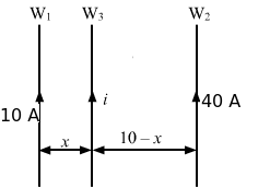
The magnetic force per unit length on a wire due to a parallel current-carrying wire is given by
Fl = μ0i1i22πdAccording to the question, wire W3 experiences no magnetic force.
∴
Fl due to wire W1=Fl due to wire W2
⇒μ010i2πx=μ040i2π(10-x)⇒10-x=4x⇒x=2 cmThus, wire W3 is placed 2 cm from the 10 A current wire.
Question 29:
Figure shows a part of an electric circuit. The wires AB, CD and EF are long and have identical resistance. The separation between the neighbouring wires is 1.0 cm. The wires AE and BF have negligible resistance and the ammeter reads 30 A. Calculate the magnetic force per unit length of AB and CD.
Figure
Answer:
Since wires AB, CD and EF have identical resistance, the current (30 A) gets equally distributed in them, that is, 10 A in each wire.
The magnetic force per unit length on a wire due to a parallel current-carrying wire is given by
Fl = μ0i1i22πd∴ Magnetic force per unit length of AB = Force due to current in CD + Force due to current in EF
Fl = μ0×10×102π×1×10-2+μ0×10×102π×2×10-2= 2×10-7×10210-2+2×10-7×1022×10-2= 2×10⁻³+10-3= 3×10⁻³ N/mSimilarly,
Magnetic force per unit length of CD = Force due to current in AB − Force due to current in EF
∵ Force on CD due to current in AB = Force due to current in EF
∴ Magnetic force per unit length of CD = 0
Question 30:
A long, straight wire is fixed horizontally and carries a current of 50.0 A. A second wire having linear mass density 1.0 × 10⁻⁴ kg m−1 is placed parallel to and directly above this wire at a separation of 5.0 mm. What current should this second wire carry such that the magnetic repulsion can balance its weight?
Answer:
Given:
Magnitude of current, i1 = 10 A
Separation between two wires, d = 5 mm
Linear mass density of the second wire, λ = 1.0 × 10⁻⁴ kgm−1
Now,
Let i2 be the current in the second wire in opposite direction.
Thus, the magnetic force per unit length on the wire due to a parallel current-carrying wire is given by
Fml = μ0i1i22πd (upwards)
Also,
Weight of the second wire, W = mg
Weight per unit length of the second wire,
Wl = λg(downwards)
Now, according to the question,
Fml = Wl⇒μ0i1i22πd=λg
⇒2×10-7×50×i25×10-3 = 1×10-4×9.8⇒i2=9.8×10-720×10-7 = 0.49 A
Question 31:
A square loop PQRS carrying a current of 6.0 A is placed near a long wire carrying 10 A as shown in figure. (a) Show that the magnetic force acting on the part PQ is equal and opposite to the part RS. (b) Find the magnetic force on the square loop.
Figure
Answer:
Given:
Current in the loop, i1 = 6 A
Current in the wire, i2 = 10 A
Now, consider an element on PQ of width dx at a distance x from the wire.

Force on the element is given by
dF=μ0i1i22πxdxForce acting on part PQ is given by
FPQ=μ0i1i22π∫13dxx =2×10-7×6×10[lnx]13 =120×10-7ln3 NSimilarly, FRS=μ0i1i22π∫31dxx =120×10-7ln 13 =-120×10-7ln3 NBoth forces are equal in magnitude, but they are opposite in direction.
(b) The magnetic field intensity due to wire on SP is given by
B=μ0i22πrForce on part SP is given by
FSP=i1Bl =μ0i1i22πlr =μ0i1i22π21(Towards right)
Force on part RQ is given by
FRQ=i1Bl =μ0i1i22πlr =μ0i1i22π23(Towards left)
Thus, the net force on the loop is given by
Fnet=FSP-FRQ =μ0i1i22π21-23 =2×10-7×6×10×43 =16×10-6 N(Towards right)
Question 32:
A circular loop of one turn carries a current of 5.00 A. If the magnetic field B at the centre is 0.200 mT, find the radius of the loop.
Answer:
Given:
No. of turns, n = 1
Magnitude of current, i = 5.00 A
Now, let the radius of the loop be r.
Thus, the magnetic field at the centre due to the current in the loop is given by
B = μ0i2r
⇒0.2×10-3 = 4π×10-7×52r⇒r=1.57×10⁻² m=1.57 cm
Question 33:
A current-carrying circular coil of 100 turns and radius 5.0 cm produces a magnetic field of 6.0 × 10⁻⁵ T at its centre. Find the value of the current.
Answer:
Given:
No. of turns, n = 100
Radius of the loop, r = 5 cm = 0.05 m
Magnetic field intensity, B = 6.0 × 10⁻⁵ T
Now, let the magnitude of current be i.
Using B=μ0ni2r, we get6.0×10-7=4π×10-7×10²×i2×0.05⇒i=60×10-74π×10-7×102 =4.777×10⁻²≈48 mA
Question 34:
An electron makes 3 × 10⁵ revolutions per second in a circle of radius 0.5 angstrom. Find the magnetic field B at the centre of the circle.
Answer:
Given:
Frequency of the electron = 3 × 10⁵
Time taken by the electron to complete one revolution, T =
1FrequencyCurrent in the circle, i =
qtRadius of the loop, r = 0.5
A°=
0.5×10⁻¹⁰ mThus, the magnetic field at the centre due to the current in the loop is given by
B = μ0I2r
= 4π×10-7×qT2×0.5×10-10 =4π×10-7×1.6×10-192×0.5×10-10×3×105 = 6×10⁻¹⁰ T
Question 35:
A conducting circular loop of radius a is connected to two long, straight wires. The straight wires carry a current i as shown in figure. Find the magnetic field B at the centre of the loop.
Figure
Answer:
As the centre of the loop, that is, point O, lies on the same line of two long, straight wires, the magnetic field at O due to each straight wire is zero.

Since wires ABC and ADC are identical, the current gets equally distributed in two parts at point A. So, the magnetic field due to ABC and ADC at O are equal in magnitude but are opposite in directions. (as shown in the figure).
∴ Net magnetic field at O = 0
Page No 252:
Question 36:
Two circular coils of radii 5.0 cm and 10 cm carry equal currents of 2.0 A. The coils have 50 and 100 turns respectively and are placed in such a way that their planes as well as the centres coincide. Find the magnitude of the magnetic field B at the common centre of the coils if the currents in the coils are (a) in the same sense (b) in the opposite sense.
Answer:
No. of turns: n1 = 50 and n2 = 100
Magnitude of currents: i1 = i2 = 2 A
Radii of loops: r1 = 5 cm and r2 = 10 cm
(a) In the same sense:
The magnetic field intensity at the centre is given by
B = μ0n1i12r1+μ0n2i22r2= 4π×10-7×50×22×5×10-2+4π×10-7×100×22×10×10-2= 4π×10-4+4π×10-4= 2×4π×10-6= 8π×10-3 T(b) In the opposite sense:
The magnetic field intensity at the centre is given by
B = μ0n1i12r1-μ0n2i22r2 =4π×10-7×50×22×5×10-2-4π×10-7×100×22×10×10-2 =0
Question 37:
Two circular coils of radii 5.0 cm and 10 cm carry equal currents of 2.0 A. The coils have 50 and 100 turns respectively and are placed in such a way that their planes as well as the centres coincide. Find the magnitude of the magnetic field B at the common centre of the coils if the currents in the coils are (a) in the same sense (b) in the opposite sense.
Answer:
Given:
No. of turns: n1 = 50 and n2 = 100
Magnitude of currents: i1 = i2 = 2 A
Radii of loops: r1 = 5 cm and r2 = 10 cm
(a) In the same sense:
The magnetic field intensity at the centre due to C1 is given by
B1=μ0n1i12r1= 4π×10-7×50×22×5×10-2= 4π×10-4 T(In the plane of paper in upward direction)
The magnetic field intensity at the centre due to C2 is given by
B2=μ0n2i22r2= 4π×10-7×100×22×10×10-2=4π×10-4 T(In the plane of paper in upward direction)
In this case, magnetic fields due to C1 and C2 at the centre are along the same direction.
Thus, the net magnetic field is given by
Bnet = B1+B2= (4π×10-4)+(4π×10-4)= 8π×10-4 T= 25.12 mT(b) When the direction of current in the two coils is opposite to each other then the magnetic fields will also point in opposite directions as shown in the figure. Hence, the net magnetic field will be obtained by the subtraction of the two magnetic fields.
Bnet = B1-B2= (4π×10-4)-(4π×10-4)=0
Question 38:
A circular loop of radius 20 cm carries a current of 10 A. An electron crosses the plane of the loop with a speed of 2.0 × 10⁶ m s−1. The direction of motion makes an angle of 30° with the axis of the circle and passes through its centre. Find the magnitude of the magnetic force on the electron at the instant it crosses the plane.
Answer:
Given:
Magnitude of current in the loop, I = 10 A
Radius of the loop, r = 20 cm = 20 × 10−2 m
Thus, the magnetic field intensity at the centre is given by
B = μ0I2rNow,
Velocity of the electron, v = 2 × 10⁶ m/s
Angle between the velocity and the magnetic field intensity, θ = 30°
Thus, the magnetic force on the electron is given by
F = evBsin θ=1.6 ×10-19×2×106×μ0i2Rsin 30°= 1.6×10-19×2×106×4π×10-7×102×20×10-2×12=16π×10-19 N
Question 39:
A circular loop of radius R carries a current I. Another circular loop of radius r(<<R) carries a current i and is placed at the centre of the larger loop. The planes of the two circles are at right angle to each other. Find the torque acting on the smaller loop.
Answer:
Given:
For the outer loop,
Magnitude of current = I
Radius of the loop = R
Thus, the magnetic field at the centre due to the larger loop is given by
B=μ0I2RLet A be the area of the smaller loop and let current i pass through it.
Now,
Angle between the area vector of the smaller loop and the magnetic field due to the larger loop = 90°
Thus, the required torque is given by
Γ = i(A →× B →) = iABsin 90°
=iπr2μ0I2R=μ0πr2Ii2R
Question 40:
A circular loop of radius r carrying a current i is held at the centre of another circular loop of radius R(>>r) carrying a current I. The plane of the smaller loop makes an angle of 30° with that of the larger loop. If the smaller loop is held fixed in this position by applying a single force at a point on its periphery, what would be the minimum magnitude of this force?
Answer:
Given:
For the outer loop,
Magnitude of current = I
Radius of the loop = R
Thus, the magnetic field at the centre due to the larger loop is given by
B = μ0I2RLet A be the area of the smaller loop and let current i pass through it.
Now,
Angle between the area vector of the smaller loop and the magnetic field due to the larger loop = 30°
Thus, the torque on the smaller loop is given by
Γ = i(A →× B →) = iABsin 30°
=iπr2μ0I4R=μ0πr2Ii4RIf the smaller loop is held fixed in its position, then
Torque due to the magnetic field = Torque due to the external force at its periphery
⇒Fr = μ0πr2Ii4R⇒F = μ0πIir4RThis is the minimum magnitude of force to balance the given condition.
Question 41:
Find the magnetic field B due to a semicircular wire of radius 10.0 cm carrying a current of 5.0 A at its centre of curvature.
Answer:
Given:
Magnitude of current, I = 5 A
Radius of the semi-circular wire, r = 10 cm
∴ Required magnetic field at the centre of curvature
B = 12×μ0i2r = 10-7×510×10-2 = 5π×10-6 = 1.6×10⁻⁵ T
Question 42:
A piece of wire carrying a current of 6.00 A is bent in the form of a circular are of radius 10.0 cm, and it subtends an angle of 120° at the centre. Find the magnetic field B due to this piece of wire at the centre.
Answer:

Given:
Magnitude of current, I = 6 A
Radius of the semi-circular wire, r = 10 cm
Angle subtended at the centre, θ = 120° =
2π3∴ Required magnetic field at the centre of curvature
B= μ0i2rθ2π= 4×10-7×52×10×10-2×2π3×2π= 4π×10-6= 1.26×10⁻⁵ T
Question 43:
A circular loop of radius r carries a current i. How should a long, straight wire carrying a current 4i be placed in the plane of the circle so that the magnetic field at the centre becomes zero?
Answer:
Given:
Magnitude of current = i
Radius of the loop = r
Magnetic field due to the loop at its centre,
B l = μ0i2rLet a straight wire carrying 4i current be placed at a distance x from the centre such that the magnetic fields of the loop and the wire are of equal magnitude but in opposite direction at O.
Magnetic field due to the wire at the centre of the loop,
Bw = μ04i2πxAccording to the question,
Bl = Bw⇒μ0i2r = μ04i2πx⇒ x = 8r2π = 4rπThis means that the wire is placed
4rπfrom the centre of the loop (as shown in the figure).
Question 44:
A circular coil of 200 turns has a radius of 10 cm and carries a current of 2.0 A. (a) Find the magnitude of the magnetic field
B →at the centre of the coil. (b) At what distance from the centre along the axis of the coil will the field B drop to half its value at the centre?
(43=1·5874…)
Answer:
Number of turns, n = 200
Radius of the coil, r = 10 cm
Current in the coil, i = 2A
(a) Let the magnetic field at the centre of the coil is B.
As the relation for magnetic field at the centre of a circular coil is given by
B = nμ0i2r=200×4π×10-7×22×10×10-2= 2.51×10-3= 12.56 mT(b) As magnetic field at any point P (say) on the axis of the circular coil is given by
BP = nμ0ir22(x2+r2)32Where x is the distance of the point from the centre of the coil.
As per the question
12Bcentre = BP⇒12nμ0i2r = nμ0ir22(x2+r2)32⇒(x2+r2)32 = 2r3⇒(x2+r2) = 41/3r2⇒x2 + r2 = 1.58r2⇒x =0.766 r⇒x = ±7.66 cmMagnetic field will drop to half of its value at the centre if the distance of that point from the centre of the coil along the axis of coil is equal to 7.66 cm.
Question 45:
A circular loop of radius 4.0 cm is placed in a horizontal plane and carries an electric current of 5.0 A in the clockwise direction as seen from above. Find the magnetic field (a) at a point 3.0 cm above the centre of the loop (b) at a point 3.0 cm below the centre of the loop.
Answer:
Given:
Magnitude of current, I = 5.0 A
Radius of the loop, r = 4.0 cm

(a) The magnetic field intensity B on point O at a distance x on the axial line is given by
B = μ02ir2(x2+r2)3/2
=4π×10-7×5×16×10-42[(9×16)×10-4]3/2=4π×80×10-112×125×10-6=4.019×10-5 T (in downward direction)(b) The magnetic field intensity B on point O’ at a distance x on the axial line is given by
B = μ02ir2(x2+r2)3/2
=4π×10-7×5×16×10-42[(9×16)×10-4]3/2=4π×80×10-112×125×10-6=4.019×10-5 T (in downward direction)
Question 46:
A charge of 3.14 × 10⁻⁶ C is distributed uniformly over a circular ring of radius 20.0 cm. The ring rotates about its axis with an angular velocity of 60.0 rad s−1. Find the ratio of the electric field to the magnetic field at a point on the axis at a distance of 5.00 cm from the centre.
Answer:

Given:
Magnitude of charges, q = 3.14 × 10⁻⁶ C
Radius of the ring,
r=20 cm=20×10-2 m
Angular velocity of the ring,
ω=60 rad/sTime for 1 revolution =
2π60
∴Current, i = qt = 3.14×10-6×602π=30×10-6 AIn the figure, E1 and E2 denotes the electric field at a point on the axis at a distance of 5.00 cm from the centre due to small element 1 and 2 of the ring respectively.
E is the resultant electric field due to the entire ring at a point on the axis at a distance of 5.00 cm from the centre.
The electric field at a point on the axis at a distance x from the centre is given by
E = xq4πε0(x2+r2)32The magnetic field at a point on the axis at a distance x from the centre is given by
B = μ02ir2(x2+r2)3/2EB = xq4πε0(x2+r2)32μ02ir2(x2+r2)3/2= 9×109×3.14×10-6×2×(20.6)3×10-625×10-4×4π×10-14×12= 9×3.14×2×(20.6)325×4π×12= 1.88×10¹⁵ m/s
Question 47:
A thin but long, hollow, cylindrical tube of radius r carries i along its length. Find the magnitude of the magnetic field at a distance r/2 from the surface (a) inside the tube (b) outside the tube.
Answer:
(a) The magnetic field inside any conducting tube is always zero.
∴ Magnetic field inside the tube at a distance r/2 from the surface = 0
(b) Let the point outside the tube with distance
r2be P.
∴ Net distance from centre, r‘ =
r+r2=3r2Consider an Amperian loop, as shown in the figure.
Length of the loop, l =
2π×32r=3πrCurrent enclosed in the loop = i
On applying Ampere’s law, we get
∫B.dl=μ0i⇒B×3πr=μ0i⇒B=μ0i3πr
Question 48:
A long, cylindrical tube of inner and outer radii a and b carries a current i distributed uniformly over its cross section. Find the magnitude of the magnitude filed at a point (a) just inside the tube (b) just outside the tube.
Answer:

a) The magnetic field inside any conducting tube is always zero.
∴ Magnetic field just inside the tube is zero.
(b) Let the point outside the tube with distance b be P.
Consider an Amperian loop, as shown in the figure.
Length of the loop, l =
2π×b=2πbCurrent enclosed in the loop = i
On applying Ampere’s law, we get
∫B.dl=μ0i⇒B×2πb=μ0i⇒B=μ0i2πb
Question 49:
A long, cylindrical wire of radius b carries a current i distributed uniformly over its cross section. Find the magnitude of the magnetic field at a point inside the wire at a distance a from the axis.
Answer:
Given:
Magnitude of current = i
Radius of the wire = b

For a point at a distance a from the axis,
Current enclosed,
i’=iπb2×πa2By Ampere’s circuital law,
∮B.dl = μ0i’For the given conditions,
B×2πa= μ0iπb2×πa2⇒B=μ0ia2πb2
Question 50:
A solid wire of radius 10 cm carries a current of 5.0 A distributed uniformly over its cross section. Find the magnetic field B at a point at a distance (a) 2 cm (b) 10 cm and (c) 20 cm away from the axis. Sketch a graph B versus x for 0 < x < 20 cm.
Answer:

Given:
Magnitude of current, i = 5 A
Radius of the wire, b
=10 cm=10×10-2 mFor a point at a distance a from the axis,
Current enclosed,
i’ = iπb2×πa2By Ampere’s circuital law,
∮B.dl = μ0i’For the given conditions,
B×2πa = μ0iπb2×πa2⇒B = μ0ia2πb2 …1
(a) a=2 cm=2×10⁻² mAgain, using the circuital law, we get
B = 4π×10-7×5×2×10-22π×10-2= 2×10⁻⁶ T=2 μT(b) On putting
a = 10 cm = 10×10-2 min (1), we get
B = 10
μT(c)Using the circuital law, we get
∮B.dl = μ0iB = μ0i2πa = 2×10-7×520×10-2= 5×10⁻⁶ T = 5 μT
Question 51:
Sometimes we show an idealised magnetic field which is uniform in a given region and falls to zero abruptly. One such field is represented in figure. Using Ampere’s law over the path PQRS, show that such a field is not possible.
Figure
Answer:
Half of the loop PQRS is in the region of magnetic field and half in the area of zero magnetic field.
Let us consider a current carrying circular wire, due to which there is uniform magnetic field in the region.
Take a point A inside the loop PQRS in the region where B = 0
According to Ampere’s circuital law,
∫B.dl=μ0iIf there is current enclosed by the loop PQRS, then magnetic field B cannot be 0.
Whereas, we have taken the magnetic field at point A to be zero.
Thus, such a field is not possible.
Question 52:
Two large metal sheets carry currents as shown in figure. The current through a strip of width dl is Kdl where K is a constant. Find the magnetic field at the points P, Q and R.
Figure
Answer:
At point P,
Current, i = 0
∴ Magnetic field B = 0
At point Q,
Applying Ampere’s law, we get
∫B.dl=μ0i⇒ B.dl=μ0kdl⇒ B=μ0kAt point R,
Current, i = 0
∴ B = 0
Question 53:
Consider the situation of the previous problem. A particle having charge q and mass m is projected from the point Q in a direction going into the plane of the diagram. It is found to describe a circle of radius r between the two plates. Find the speed of the charged particle.
Answer:
Given:
Charge = q
Mass = m
Radius = r
We know that the radius described by a charged particle in a magnetic field is given by
r=mvqB
Using Ampere circuital law∫B.dl=μ0i⇒ B.dl=μ0kdl⇒ B=μ0k
⇒v=Bqrm=μ0kqrm
Question 54:
The magnetic field B inside a long solenoid, carrying a current of 5.00 A, is 3.14 × 10⁻² T. Find the number of turns per unit length of the solenoid.
Answer:
Given:
Magnitude of current, i = 5 A
Magnetic field intensity, B = 3.14 × 10⁻² T
We know that the magnetic field inside a long solenoid having n turns per unit length is given by
B=μ0ni3.14×10-2 =4π×10-7×n×5⇒n=10-220×10-7=5×103=5000 turns/m
Question 55:
A long solenoid is fabricated by closely winding a wire of radius 0.5 mm over a cylindrical nonmagnetic frame so that the successive turns nearly touch each other. What would be the magnetic field B at the centre of the solenoid if it carries a current of 5 A?
Answer:
Given:
Radius of the wire, r = 0.5 mm
Width of each turn, = diameter of the wire, 2r = 1 mm = 1 × 10⁻³ m
∴ Total number of turns in 1 m solenoid
n=11×10-3=103Magnitude of current, i=5 AUsing B=μ0ni, we getB=4π×10-7×103×5B=2π×10-3 T
Question 56:
A copper wire having resistance 0.01 ohm in each metre is used to wind a 400-turn solenoid of radius 1.0 cm and length 20 cm. Find the emf of a battery which when connected across the solenoid will cause a magnetic field of 1.0 × 10⁻² T near the centre of the solenoid.
Answer:
Given:
Resistance per unit length of the wire,
Rl= 0.01 Ω/m
Radius of the wire, r = 1.0 cm = 0.01 m
Total no. of turns, N = 400
Magnetic field intensity, B = 1.0 × 10⁻² T
Now,
Let E be the emf of the battery and R0 be the total resistance of the wire.
∴i=ER0=E0.01×2πr×400=E0.01×2×π×0.01×400The magnetic field near the centre of the solenoid is given by
B=μ0ni=1×10-2=4π×10-7×40020×10-2×E2π×4×10-2⇒E=10-2×20×10-2×2×10-210-7×4×102=1 V
Page No 253:
Question 57:
A tightly-wound solenoid of radius a and length l has n turns per unit length. It carries an electric current i. Consider a length dx of the solenoid at a distance x from one end. This contains n dx turns and may be approximated as a circular current i n dx. (a) Write the magnetic field at the centre of the solenoid due to this circular current. Integrate this expression under proper limits to find the magnetic field at the centre of the solenoid. (b) verify that if l >> a, the field tends to B = µ0ni and if a >> l, the field tends to
B=μ0nil2a. Interpret these results.
Answer:
(a) Given:
Current in the loop or circular current = indx
Radius of the loop having circular current = r
Distance of the centre of the solenoid from the circular current =
l2-xMagnetic field at the centre due to the circular loop,
B=μ02ir2(x2+r2)3/2
B=∫dB=∫01μ0a2nidx4πa2+(l-2x)23/2=∫01μ0nia2dx4πa31+l-2xa23/2=μ0ni4πa∫01dx1+l-2xa23/2=μ0ni4πa.4πa1+2al=μ0ni1+2al2(b) When a > > l,
B=μ0ni2a
Question 58:
A tightly-wound, long solenoid carries a current of 2.00 A. An electron is found to execute a uniform circular motion inside the solenoid with a frequency of 1.00 × 10⁸ rev s−1. Find the number of turns per metre in the solenoid.
Answer:
Given:
Magnitude of current in the solenoid, i = 2 A
Frequency of the electron,
f=1×10⁸ rev/sMass of the electron,
m=9.1×10⁻³¹ kgCharge of the electron,
q=1.6×10⁻¹⁹ CWe know that the magnetic field inside a solenoid is given by
B = µ0ni
If a particle executes uniform circular motion inside a magnetic field, the frequency of the particle is given by
f=qB2πm⇒B=2πmfq⇒ μ0ni=2πmfq [Using (1)]⇒n=2πmfμ0qi=2π×9.1×10-31×1×1084π×10-7×1.6×10-19×2=1420 turns/m
Question 59:
A tightly-wound, long solenoid has n turns per unit length, a radius r and carries a current i. A particle having charge q and mass m is projected from a point on the axis in a direction perpendicular to the axis. What can be the maximum speed for which the particle does not strike the solenoid?
Answer:
Given:
Magnitude of current in the solenoid = i
Number of turns per unit length = n
When a particle is projected perpendicular to the magnetic field, it describes a circular path.
And for the particle (projected from a point on the axis in a direction perpendicular to the axis) to not strike the solenoid, the maximum radius of that circular path should be r/2.
∴ Radius of the circle =
r2
We know,
Centripetal force = Magnetic force
mV2r=qVB⇒V=qBrm=qμ0nir2m
Question 60:
A tightly-wound, long solenoid is kept with its axis parallel to a large metal sheet carrying a surface current. The surface current through a width dl of the sheet is Kdl and the number of turns per unit length of the solenoid is n. The magnetic field near the centre of the solenoid is found to be zero. (a) Find the current in the solenoid. (b) If the solenoid is rotated to make its axis perpendicular to the metal sheet, what would be the magnitude of the magnetic field near its centre?
Answer:
Given:
Number of turns per unit length of the solenoid = n
(a) Since the net magnetic field near the centre of the solenoid is 0,
∴B →plate=B →solenoidUsing Guass’s law for the plate, we getBplate×2l=μ0i=μ0klBplate=μ0k2 …1For the solenoid,
Bsolenoid=μ0ni …(2)
From (1) and (2), we get
i = k2n(b) On putting the value of n in (2), we get
B →solenoid=μ0k2Now,
B →plate and B →solenoidare perpendicular to each other.
Thus, the net magnetic field near the centre of the solenoid is given by
Bnet = μ0k22+μ0k22 =μ0k2
Question 61:
A capacitor of capacitance 100 µF is connected to a battery of 20 volts for a long time and then disconnected from it. It is now connected across a long solenoid having 4000 turns per metre. It is found that the potential difference across the capacitor drops to 90% of its maximum value in 2.0 seconds. Estimate the average magnetic field produced at the centre of the solenoid during this period.
Answer:
Given:
Capacitance, C = 100 microfarad
Voltage, V = 20 V
Charge stored in the capacitor, Q = CV
= 100×10-6×20= 2×10⁻³ CIt is given that the potential difference across the capacitor drops to 90% of its maximum value.
Thus,
V’=90100×20=18 VNew charge, Q’=CV’=1.8×10⁻³ CNow, Current, i=Q-Q’t⇒i=(2-1.8)×10-32=2×10-42⇒i=1×10⁻⁴ ANo. of turns per metre, n = 4000
Thus, the average magnetic field at the centre of the solenoid is given by
B=μ0ni=4π×10-7×4000×10-4=16π×10-8 T
Chapterwise HC Verma Solutions Class 12 Physics :
- Chapter 23 – Heat and Temperature
- Chapter 24 – Kinetic Theory of Gases
- Chapter 25 – Calorimetry
- Chapter 26 – Laws of Thermodynamics
- Chapter 27 – Specific Heat Capacities of Gases
- Chapter 28 – Heat Transfer
- Chapter 29 – Electric Field and Potential
- Chapter 30 – Gauss’s Law
- Chapter 31 – Capacitors
- Chapter 32 – Electric Current in Conductors
- Chapter 33 – Thermal and Chemical Effects of Electric Current
- Chapter 34 – Magnetic Field
- Chapter 35 – Magnetic Field due to a Current
- Chapter 36 – Permanent Magnets
- Chapter 37 – Magnetic Properties of Matter
- Chapter 38 – Electromagnetic Induction
- Chapter 39 – Alternating Current
- Chapter 40 – Electromagnetic Waves
- Chapter 41 – Electric Current through Gases
- Chapter 42 – Photoelectric Effect and Wave Particle Duality
- Chapter 43 – Bohr’s Model and Physics of the Atom
- Chapter 44 – X-rays
- Chapter 45 – Semiconductors and Semiconductor Devices
- Chapter 46 – The Nucleus
- Chapter 47 – The Special Theory of Relativity
About the Author – HC Verma
HC Verma, the author of many popular and well-renowned Physics books, was born on 8 April 1952. Passing out from one of the most prestigious colleges of the country, IIT Kanpur, he worked as an experimental physicist in the Department of Nuclear Physics.
His most famous works which he is known for include the two-volume Concepts of Physics. He also worked for the social upliftment of the economically weaker children through his organization named Shiksha Sopan. He is also the recipient of the Padma Shri, which is considered India’s fourth-highest civilian award. He received the same because of his contribution and valuable work in the field of Physics.